Project Overview
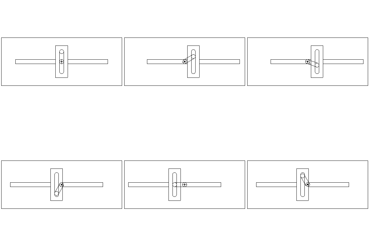
This project focused on designing, fabricating, and iterating a mechanical embosser that converts continuous rotational input into high-force linear stamping motion via a Scotch yoke mechanism.
Skills Demonstrated & Key Accomplishments
- Skills Demonstrated: Mechanism Design & Kinematics (Scotch Yoke & Gear Trains), 3D CAD Assemblies & Exploded Views (SolidWorks), Multi-Process Prototyping (FDM 3D Printing, Laser Cutting, Machining), Root-Cause Failure Analysis.
- Resolved Mechanism Jamming: Diagnosed off-axis binding in Prototype V1 and engineered a custom yoke-gear stabilizing hub with revised axial gear spacing to keep the slider colinear under load.
- Friction & Material Optimization: Replaced laser-cut birch plywood gears with FDM 3D-printed PLA gears, significantly reducing tooth-to-tooth friction and sliding resistance against the Scotch yoke slot.
- Rigid Structural Packaging: Integrated T-slot aluminum extrusions with laser-cut acrylic mounting brackets to minimize frame deflection during stamping strokes.
Engineering First Principles & Approach
A Scotch yoke mechanism converts rotational motion (ω) of a crank pin at radius (r) into pure sinusoidal linear displacement (x = r cos θ), delivering peak mechanical advantage near bottom dead center where the stamping die contacts the target material.
To prevent the linear slider from binding inside its guide rails, lateral reaction forces caused by friction at the sliding pin-slot interface and gear mesh misalignment must be minimized:
- Consistent Force Application: Concentrating stamping force normal to the die face at the bottom of the stroke.
- Alignment & Tolerance Control: Constraining out-of-plane gear wobble and axial shaft play.
- Low-Friction Tribology: Selecting low-friction mating materials for the gear teeth and sliding yoke slot.
Design Iteration
-
Kinematics & Problem Definition
The design specification required using a Scotch yoke mechanism to repeatedly emboss a target substrate without manual intervention.
-
CAD Modeling & Multi-Material Architecture
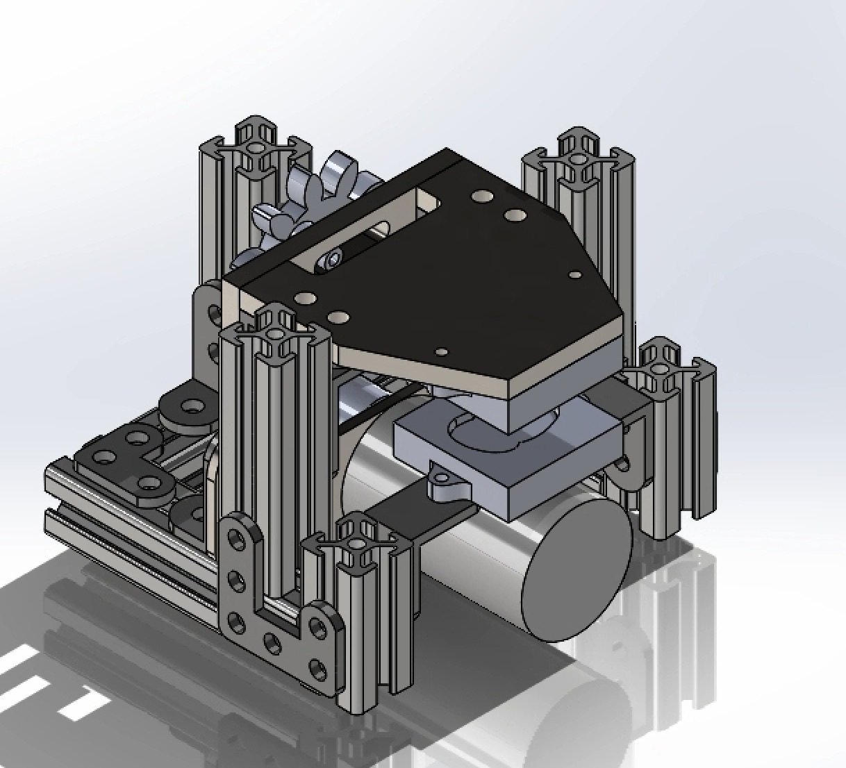
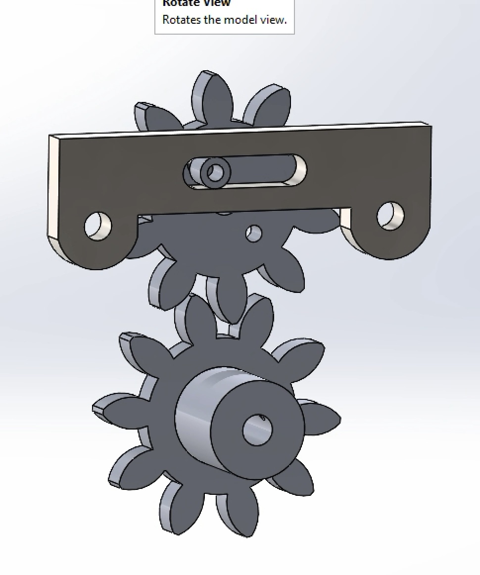
In SolidWorks, we designed a rigid frame using aluminum extrusions paired with laser-cut acrylic brackets for rapid assembly and visual inspection of the internal drive train.
-
Prototype V1 Testing & Failure Diagnosis
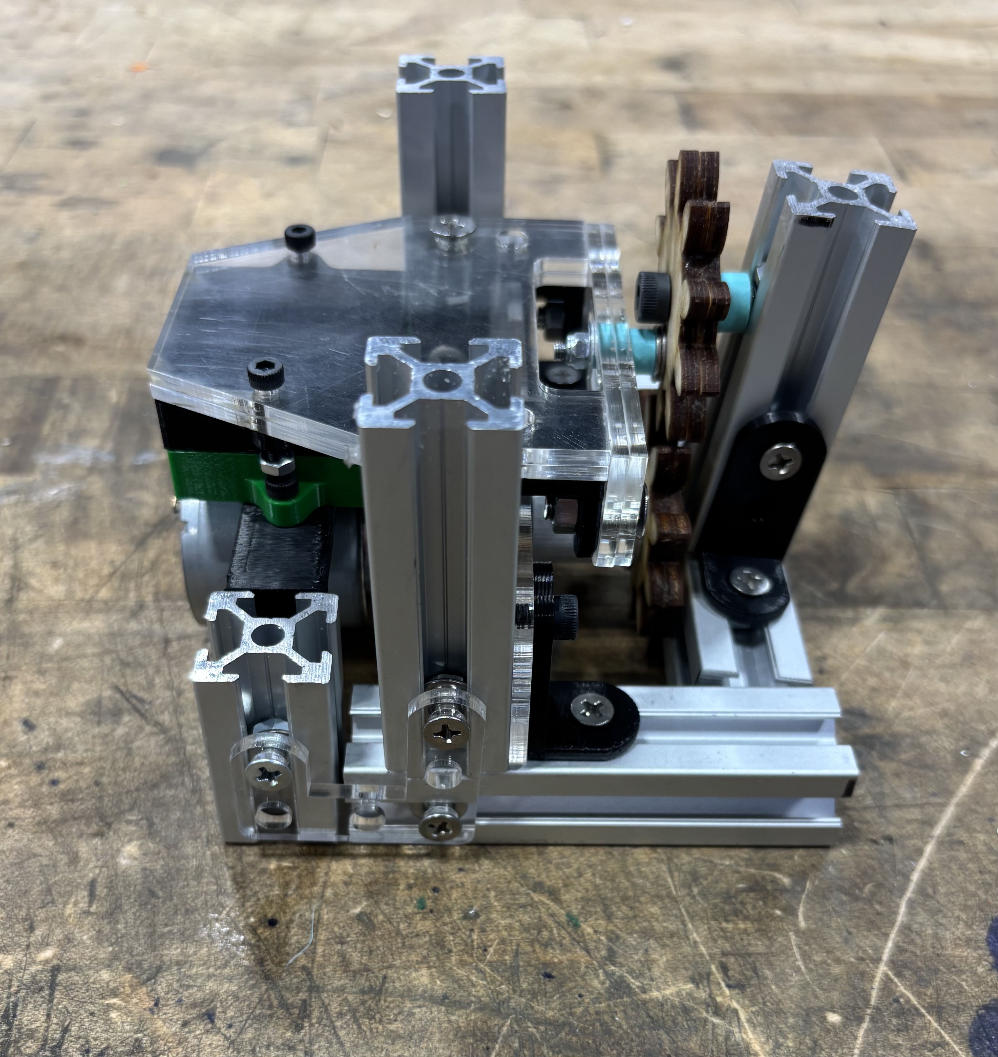
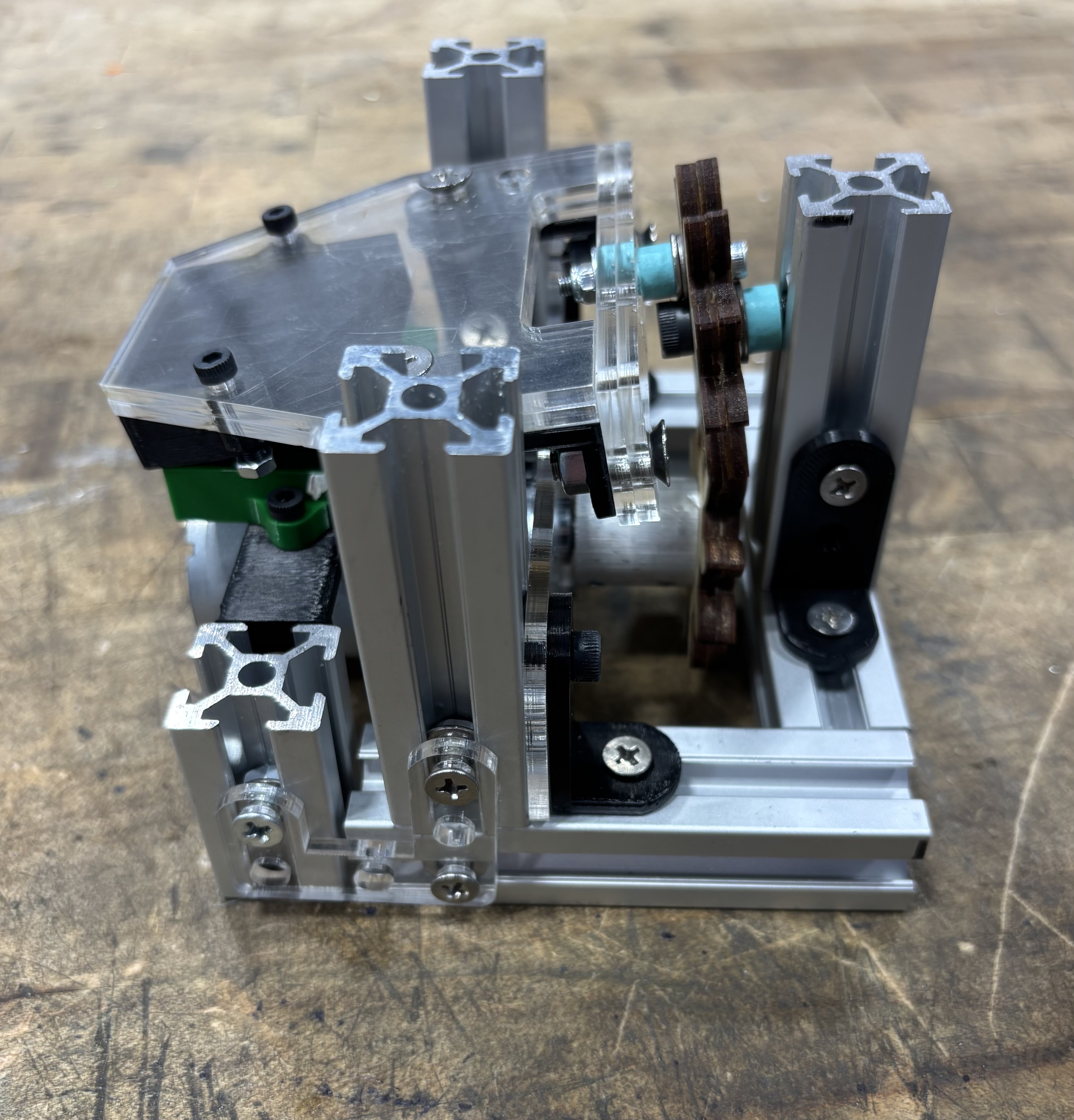
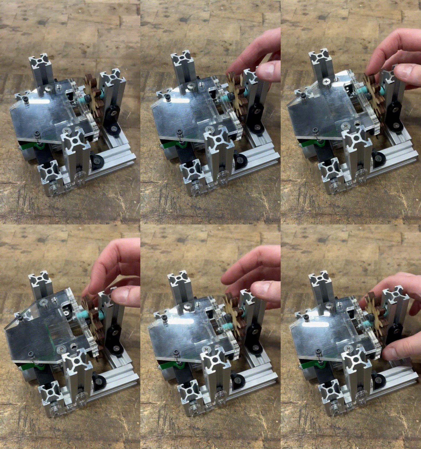
After fabricating parts via 3D printing, laser cutting, and machining, benchtop testing of Prototype V1 revealed severe mechanical jamming midway through the stroke. Root-cause inspection showed that axial wobble in the unhubbed yoke gear combined with high surface friction in the laser-cut birch plywood gears caused the pin to cock sideways in the yoke slot.
-
Prototype V2: Hub Redesign & PLA Gear Upgrade
To eliminate jamming, we executed two targeted engineering changes:
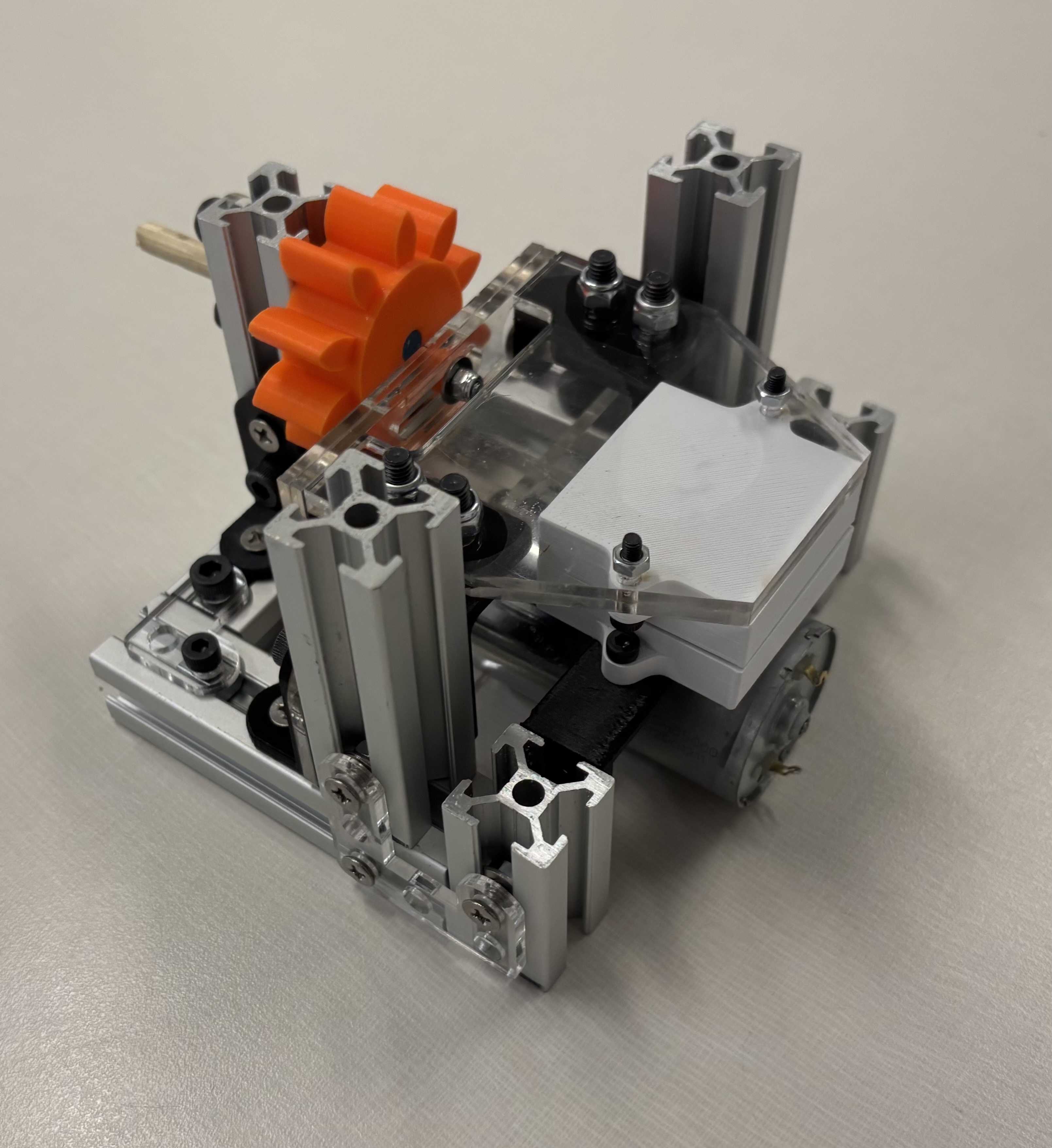
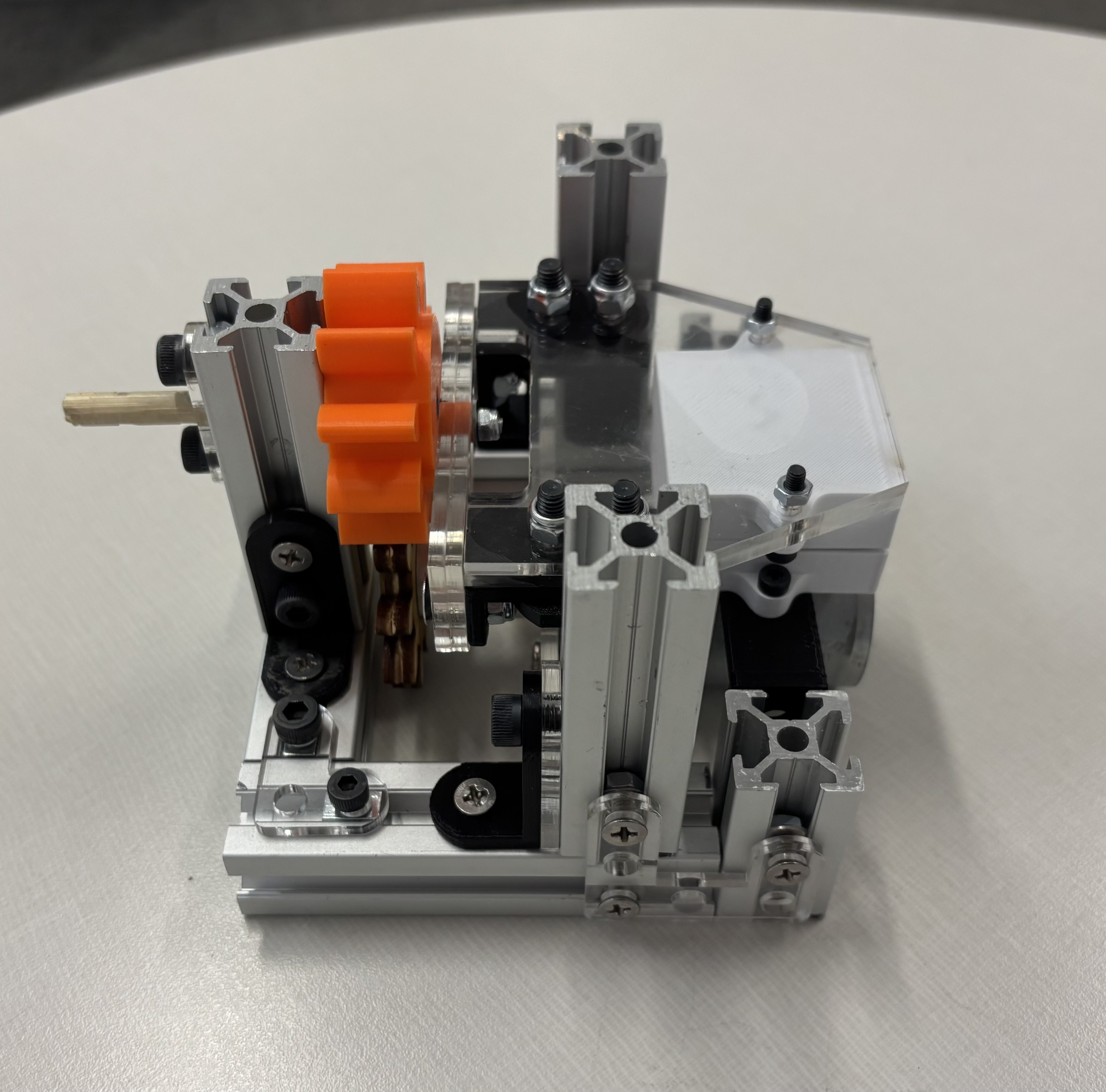
- Geometric Alignment: Redesigned the gear spacing and integrated a wide stabilizing hub onto the yoke gear to eliminate out-of-plane tilt.
- Material Tribology: Switched the gear train from laser-cut birch plywood to 3D-printed PLA, drastically lowering both gear-mesh friction and sliding friction against the Scotch yoke.
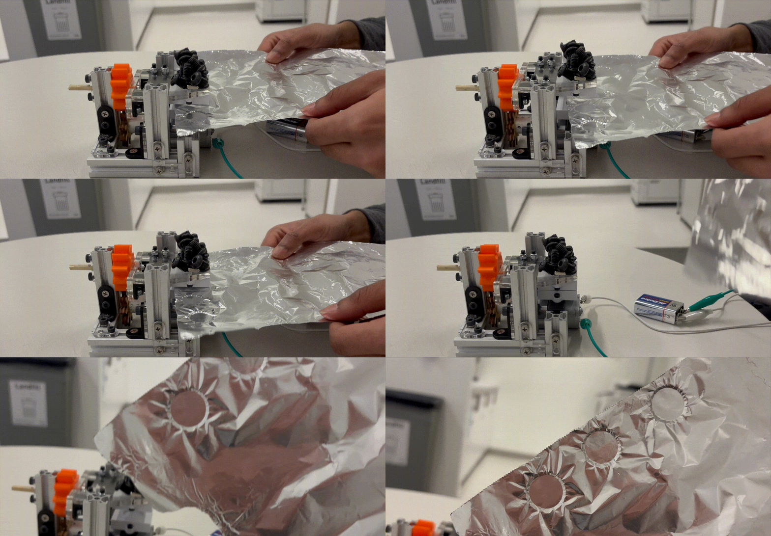
Following these upgrades, Prototype V2 operated smoothly and continuously without jamming.
-
Full Assembly & Exploded View
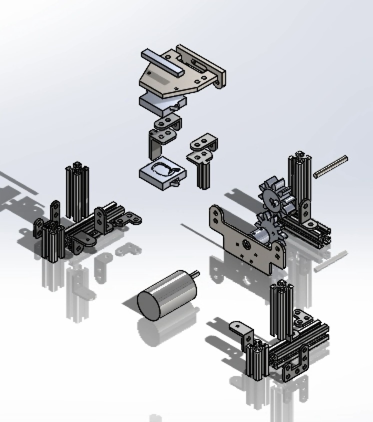
The full SolidWorks exploded assembly illustrates the complete mechanical stackup, fastener locations, aluminum frame, acrylic brackets, PLA gear train, and Scotch yoke die assembly.
Final Outcome & Reflection
Outcome: The iterated prototype achieved smooth, repeatable reciprocating motion and successfully embossed target materials without mechanical binding.
Reflection & Version 3.0 Improvements: During final testing, motor torque at the current gear ratio required adding supplementary dead-weight atop the embossing dies to achieve deep impressions. If building Version 3.0, I would increase the gear reduction ratio to trade rotational speed (ω) for higher mechanical torque (τ) and stamping force, and add linear ball bearings or bronze bushings on the vertical guide rods to further minimize parasitic friction loss.