Project Overview
This project models and analyzes the mechanical performance of a Ti-6Al-4V titanium dental implant embedded in multi-layer jawbone (cortical and cancellous bone) under oblique masticatory loading in SolidWorks Simulation.
Skills Demonstrated & Key Accomplishments
- Skills Demonstrated: Finite Element Analysis (SolidWorks Simulation), Parametric 3D CAD Modeling (SolidWorks), Curvature-Based Mesh Refinement, Biomechanical Boundary Condition Setup, Design Optimization.
- 38.5% Stress Reduction: Conducted a parametric study across three implant neck diameters (4.0 mm, 4.2 mm, and 4.5 mm), identifying 4.2 mm as optimal by reducing peak Von Mises stress from 200 MPa to 123 MPa.
- Safety Margin Improvement: Increased the minimum Factor of Safety (FOS) from a marginal 1.143 (standard 4.0 mm design) to 2.006 (4.2 mm design), surpassing the clinical target threshold of FOS > 1.5 [2].
- Mesh Artifact & Load-Transfer Diagnosis: Identified localized stress singularities and cortical bone overloading in the oversized 4.5 mm configuration (309 MPa, FOS 0.831), proving that thicker geometry does not monotonically reduce system stress.
Engineering First Principles & Background
When an occlusal bite force (F = 200 N) strikes an implant at an oblique angle (θ = 45°), it decomposes into both an axial compressive component (Fy = F cos 45° ≈ 141.4 N) and a lateral bending component (Fx = F sin 45° ≈ 141.4 N).
From first-principles mechanics, the lateral component induces a bending moment (M) peaking at the crestal bone-implant interface (the implant neck), where bending stress scales inversely with the section modulus (σb = Mc / I, where I = πd4 / 64). However, in a composite bone-implant assembly, expanding the implant neck diameter (d) also thins the surrounding stiff cortical bone (E = 13.7 GPa) and alters thread geometry. Using FEA allows us to evaluate this structural trade-off before clinical prototyping.
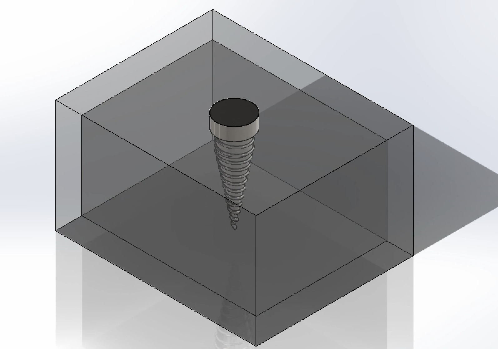
The CAD assembly models a cylindrical neck and threaded, tapering titanium body embedded in an inner cancellous bone core surrounded by a dense outer cortical bone layer.
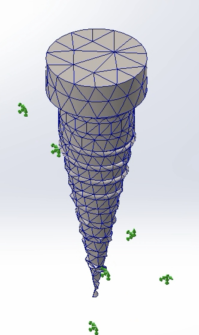
A blended curvature-based mesh was applied to accurately resolve stress concentrations along the fine helical thread roots.
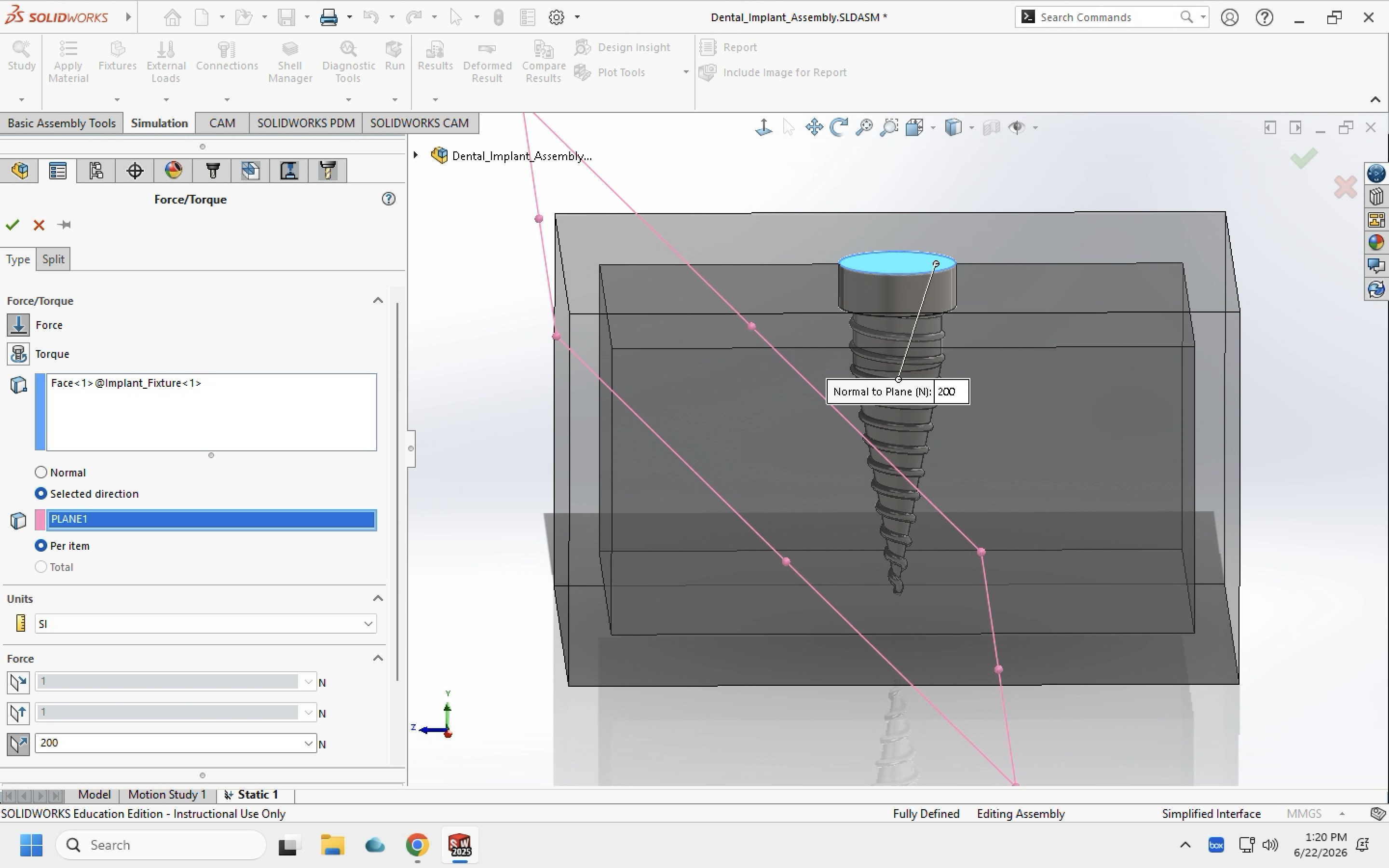
An external load of 200 N was applied to the top face of the implant neck at an oblique angle of 45° to simulate worst-case human molar bite force.
Analysis Setup & Boundary Conditions
- Simulation Software: SolidWorks Simulation
- Implant Material: Titanium Alloy (Ti-6Al-4V)
- Loading Condition: 200 N oblique load at 45°
- Anatomical Support Model: Cortical bone outer shell + cancellous bone core
- Contact Assumption: Fully osseointegrated (bonded interface)
- Primary Outputs: Von Mises Stress (MPa), Resultant Displacement (mm), Factor of Safety (FOS)
Material Properties
Isotropic linear-elastic material properties were sourced from published dental implant FEA literature [1]:
| Material | Elastic Modulus (GPa) | Poisson's Ratio | Yield Strength (MPa) |
|---|---|---|---|
| Titanium Ti-6Al-4V | 104.8 | 0.31 | 827 |
| Cortical Bone | 13.7 | 0.30 | 114 |
| Cancellous Bone | 1.37 | 0.30 | 19 |
Parametric Results Summary
| Neck Diameter | Max Von Mises Stress (MPa) | Max Displacement (mm) | Minimum FOS |
|---|---|---|---|
| 4.0 mm (Standard) | 200 MPa | 7.97 × 10⁻³ mm | 1.143 |
| 4.5 mm (Oversized) | 309 MPa | 7.39 × 10⁻³ mm | 0.831 (Failure < 1.0) |
| 4.2 mm (Optimal) | 123 MPa (-38.5%) | 6.88 × 10⁻⁴ mm | 2.006 (Pass > 1.5) |
Detailed Simulation Results
-
Baseline Design — Neck Diameter: 4.0 mm
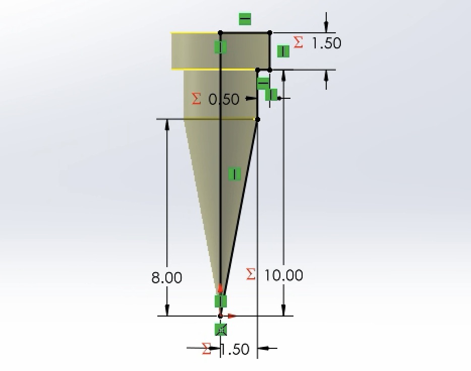
The baseline simulation evaluated standard commercial implant dimensions.
-
Von Mises Stress:
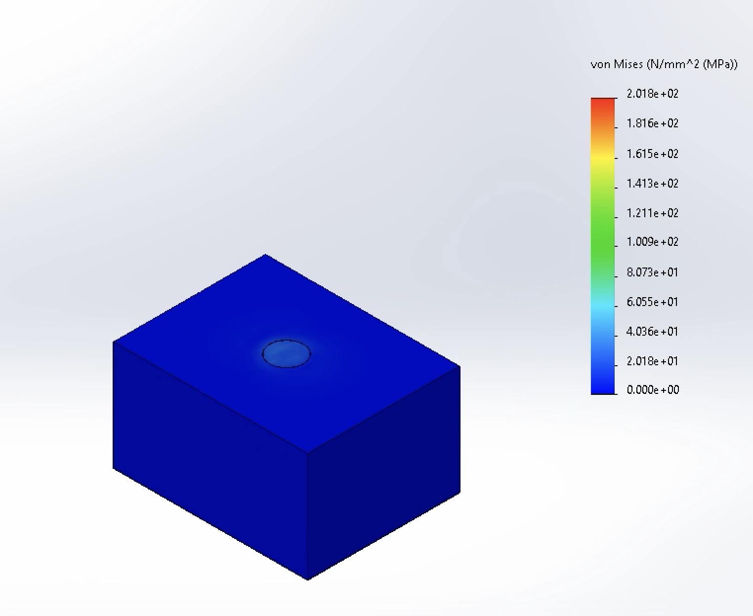
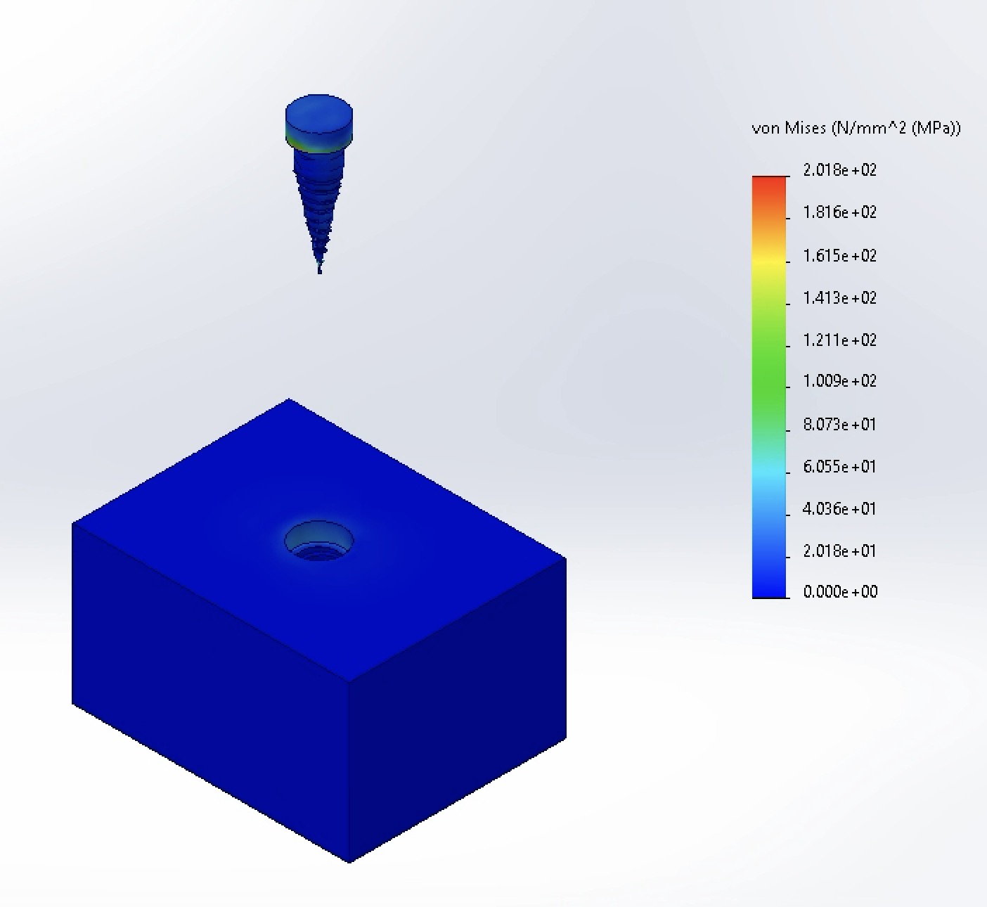
Peak stress reached 200 MPa, concentrated primarily at the base of the implant neck and the first coronal threads where bending moment is highest.
-
Displacement:
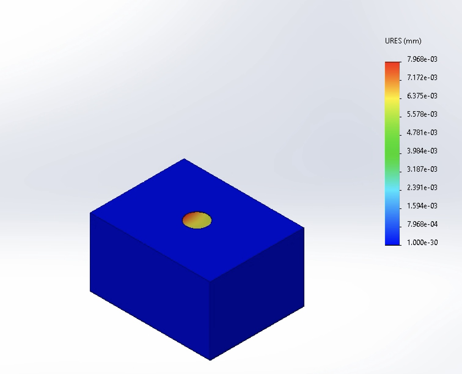
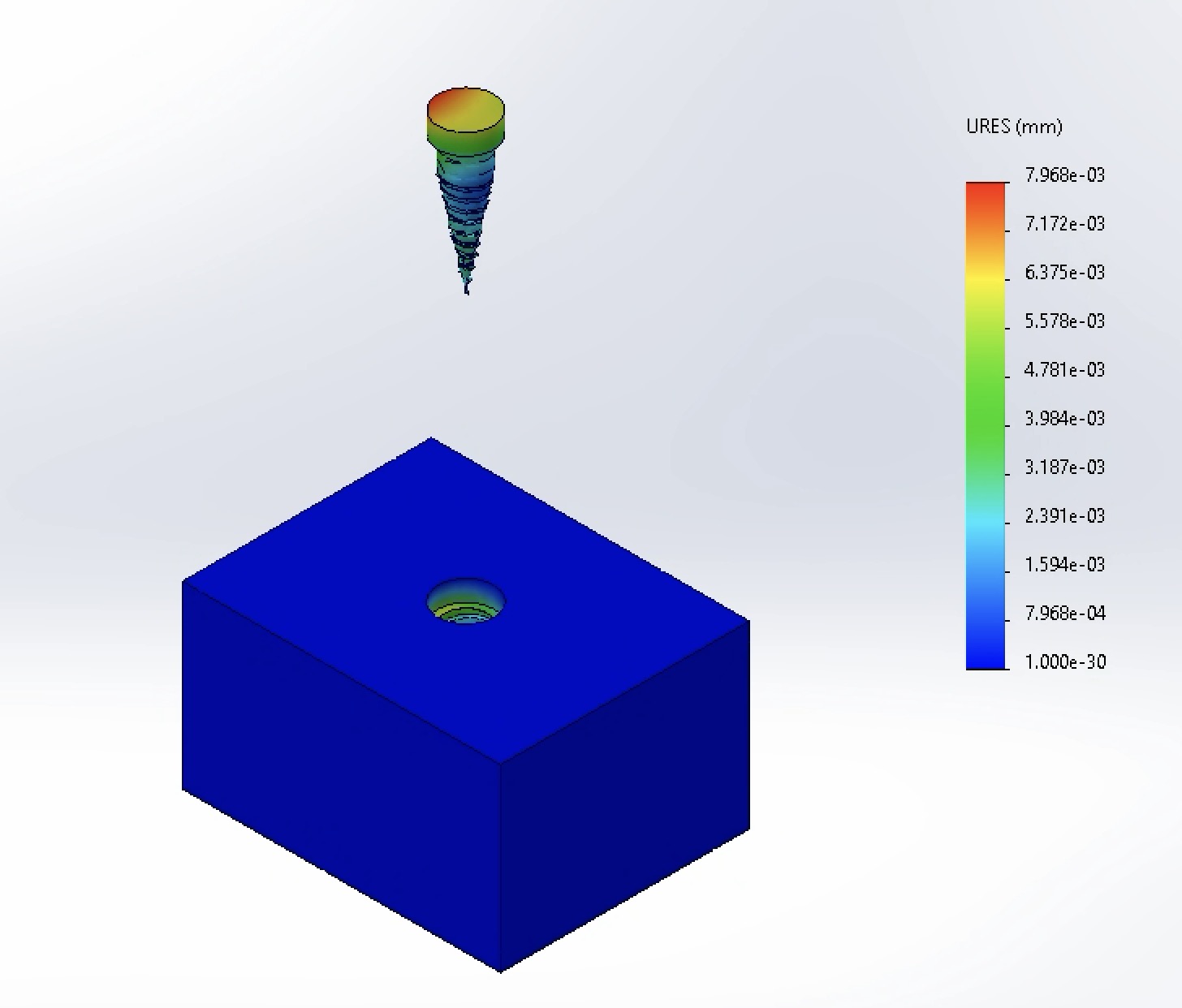
Maximum displacement was 7.968 × 10⁻³ mm at the coronal head of the implant, indicating high structural stiffness when osseointegrated.
-
Factor of Safety:
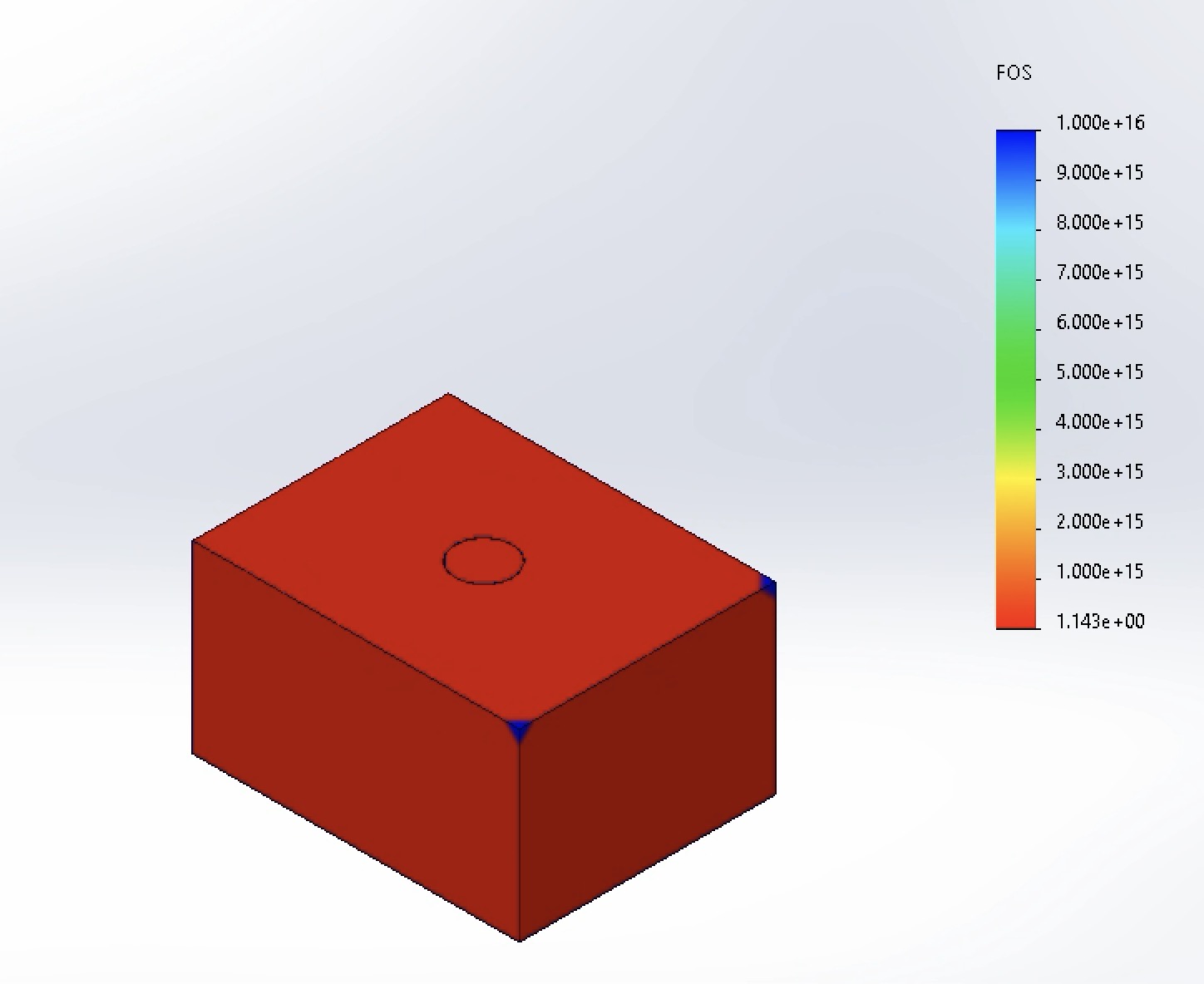
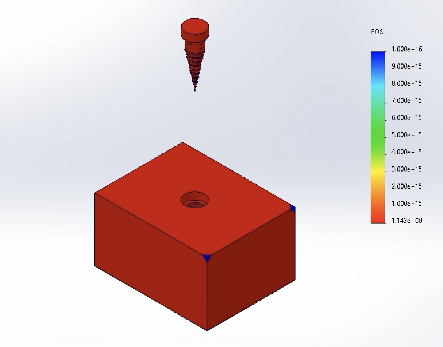
The minimum Factor of Safety was 1.143. While above yielding (1.0), this falls short of the recommended clinical design margin of FOS > 1.5 [2].
-
Von Mises Stress:
-
Iteration 1 — Neck Diameter: 4.5 mm
-
Von Mises Stress:
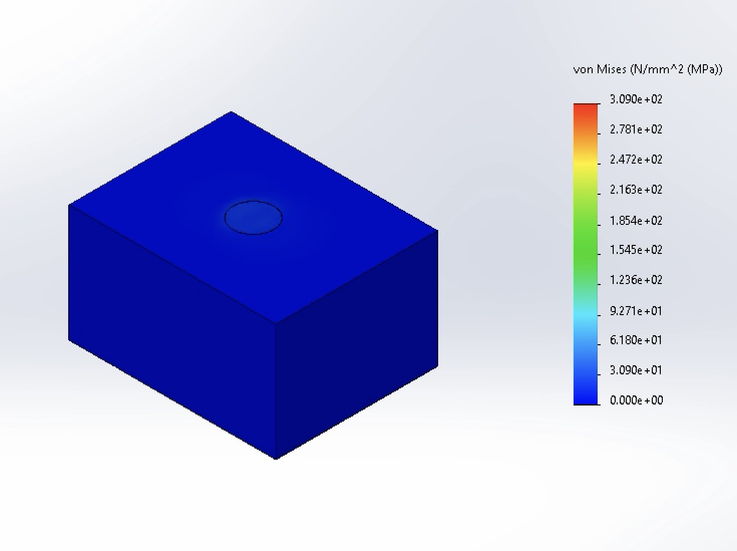
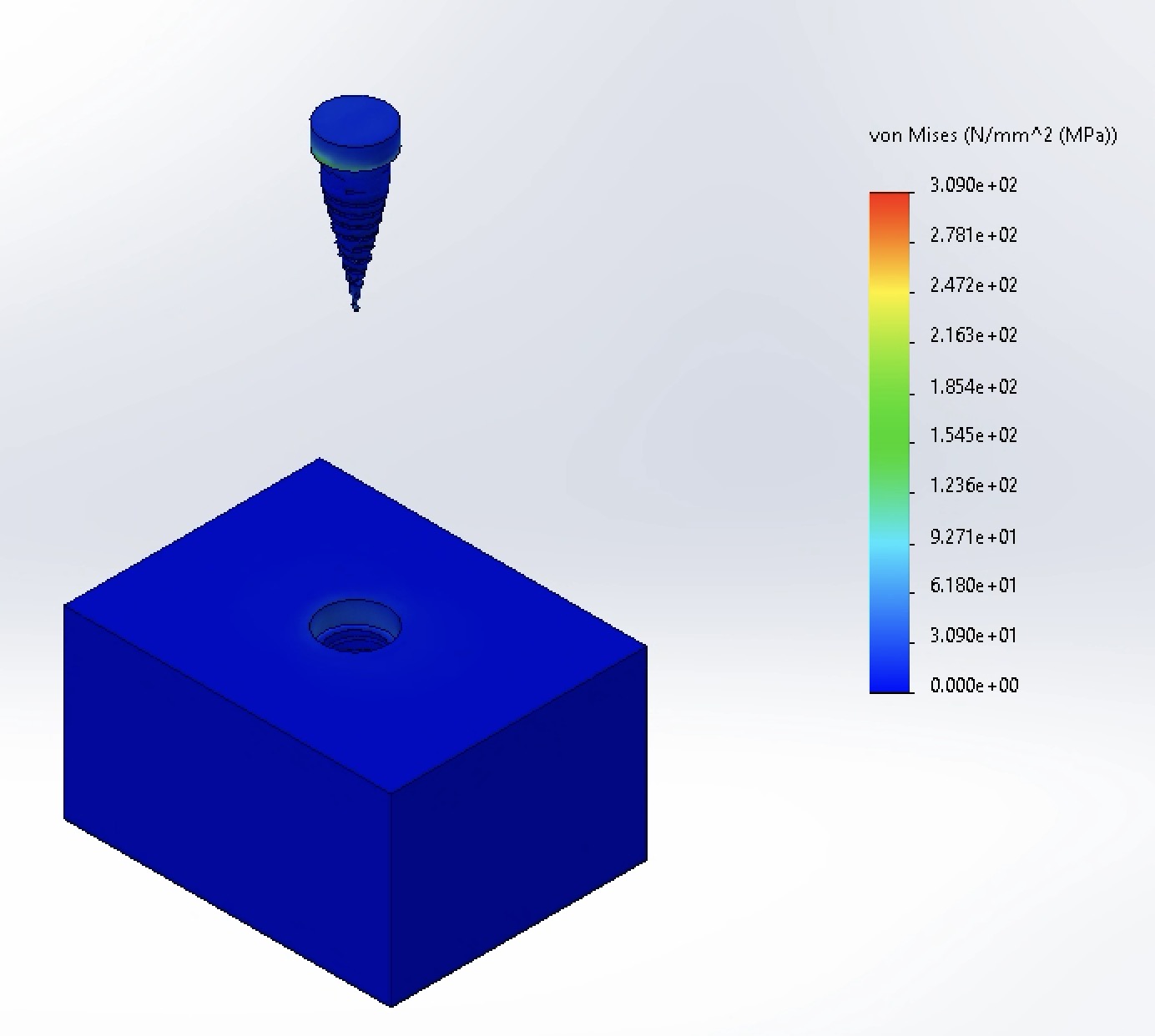
Increasing the neck diameter to 4.5 mm unexpectedly spiked maximum stress to 309 MPa. Visual contour inspection indicates that this peak is highly localized—attributable to sharp geometric transitions at the thread-neck junction (mesh singularities) and increased load transfer into the thinned surrounding cortical bone.
-
Displacement:
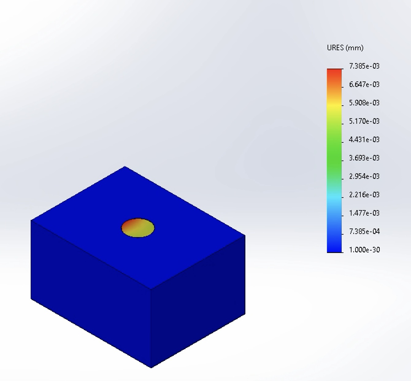
Maximum displacement decreased to 7.385 × 10⁻³ mm (down from 7.968 × 10⁻³ mm), confirming higher global bending stiffness despite the localized stress concentration.
-
Factor of Safety:
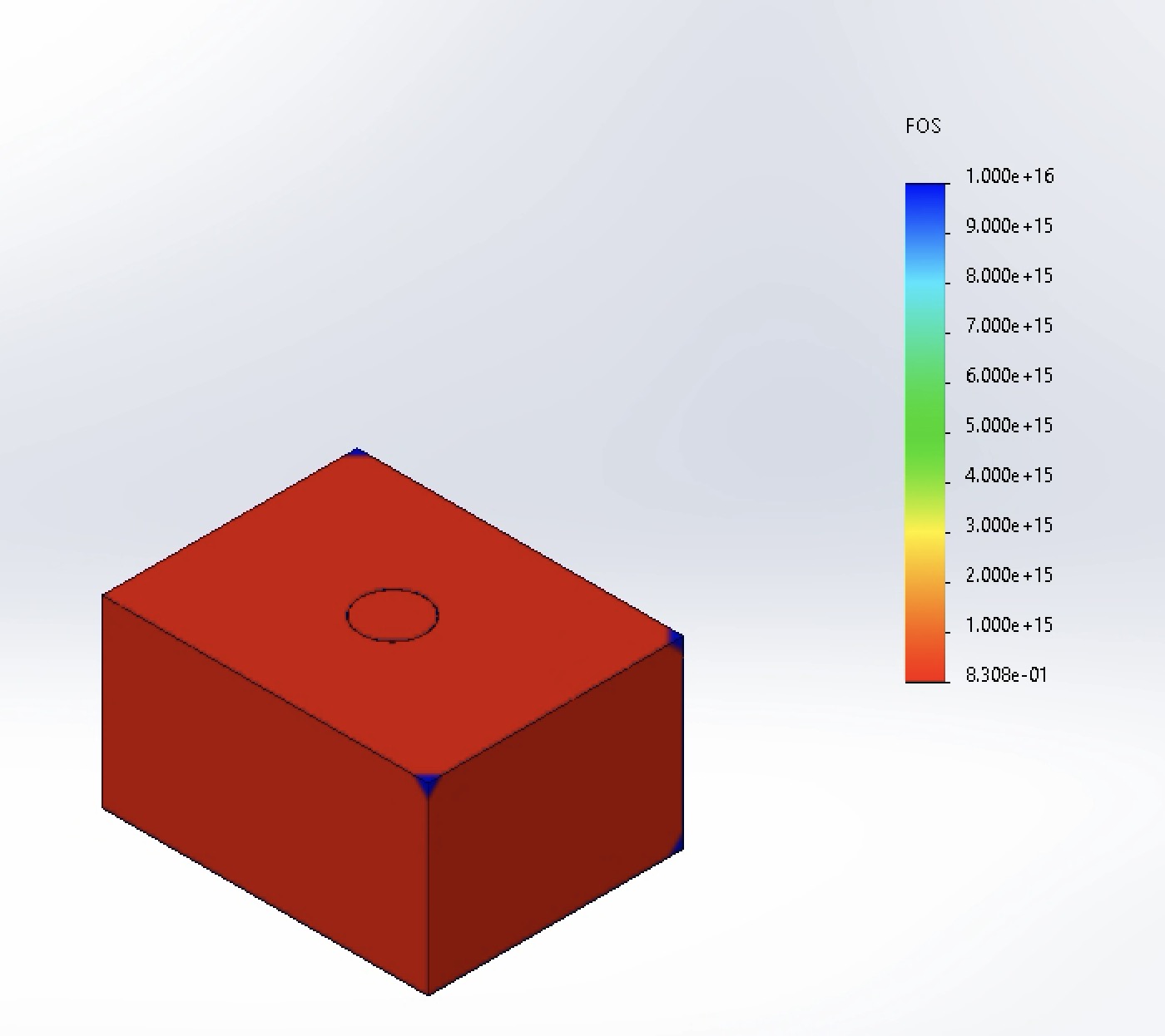
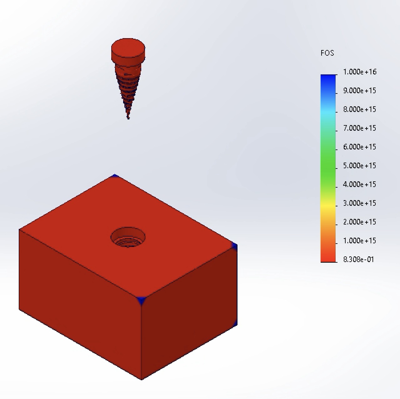
Minimum FOS dropped to 0.831 (below 1.0), indicating local yielding risk at the bone-implant crest.
-
Von Mises Stress:
-
Iteration 2 (Optimal) — Neck Diameter: 4.2 mm
-
Von Mises Stress:
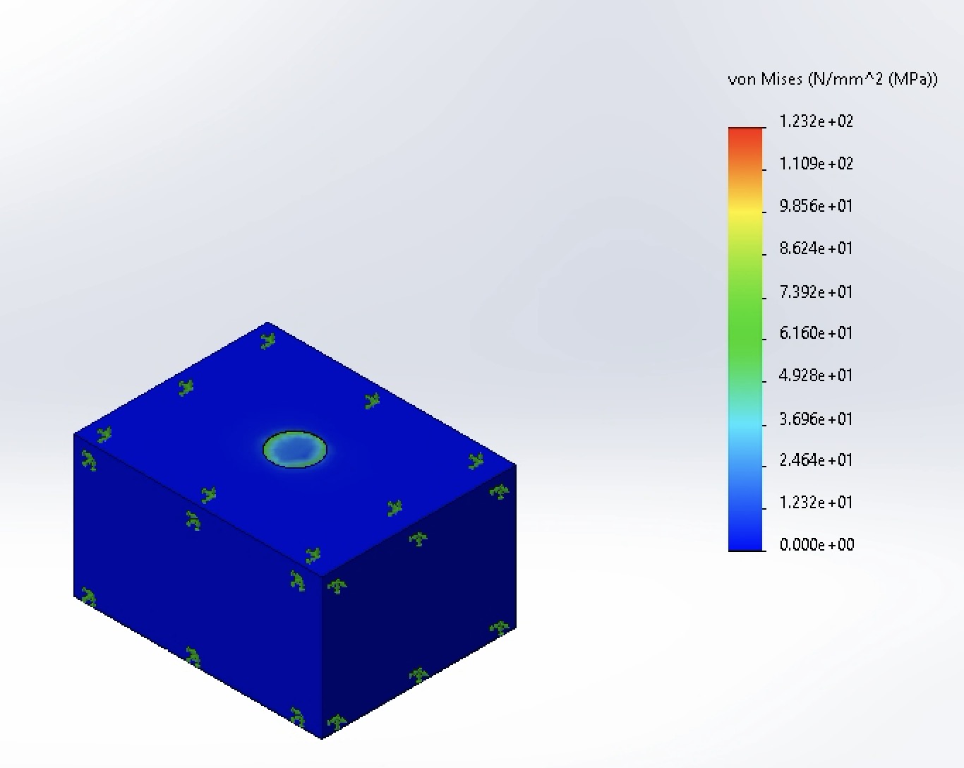
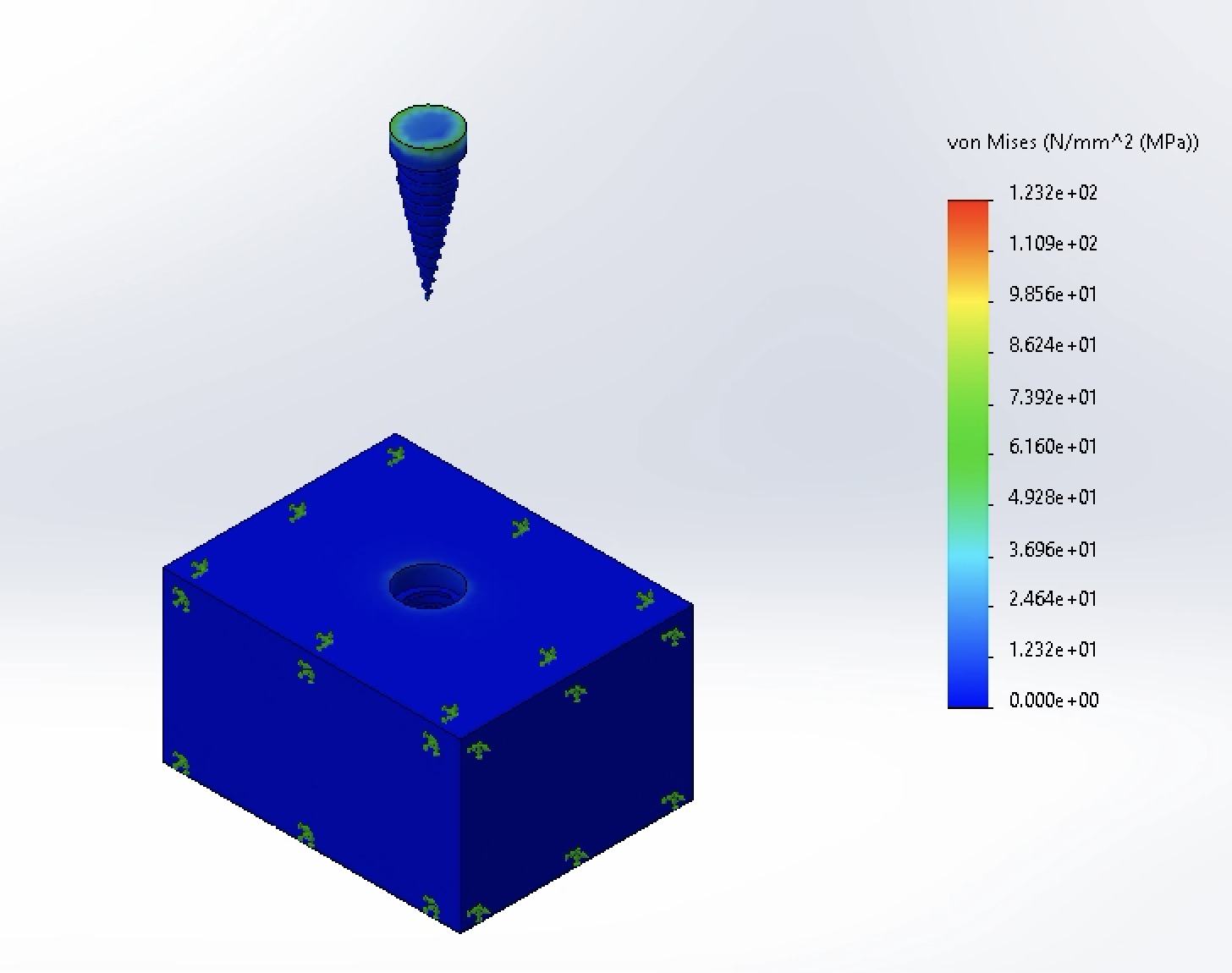
A moderate diameter increase to 4.2 mm achieved the lowest peak stress across all trials at 123 MPa—a 38.5% reduction compared to the 4.0 mm baseline.
-
Displacement:
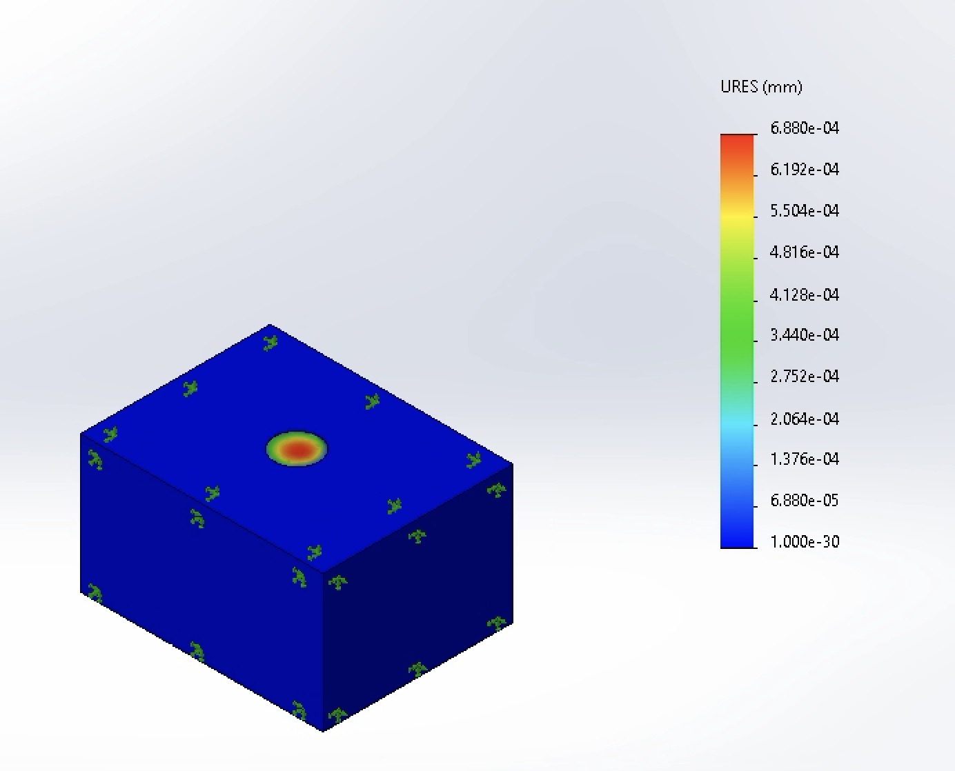
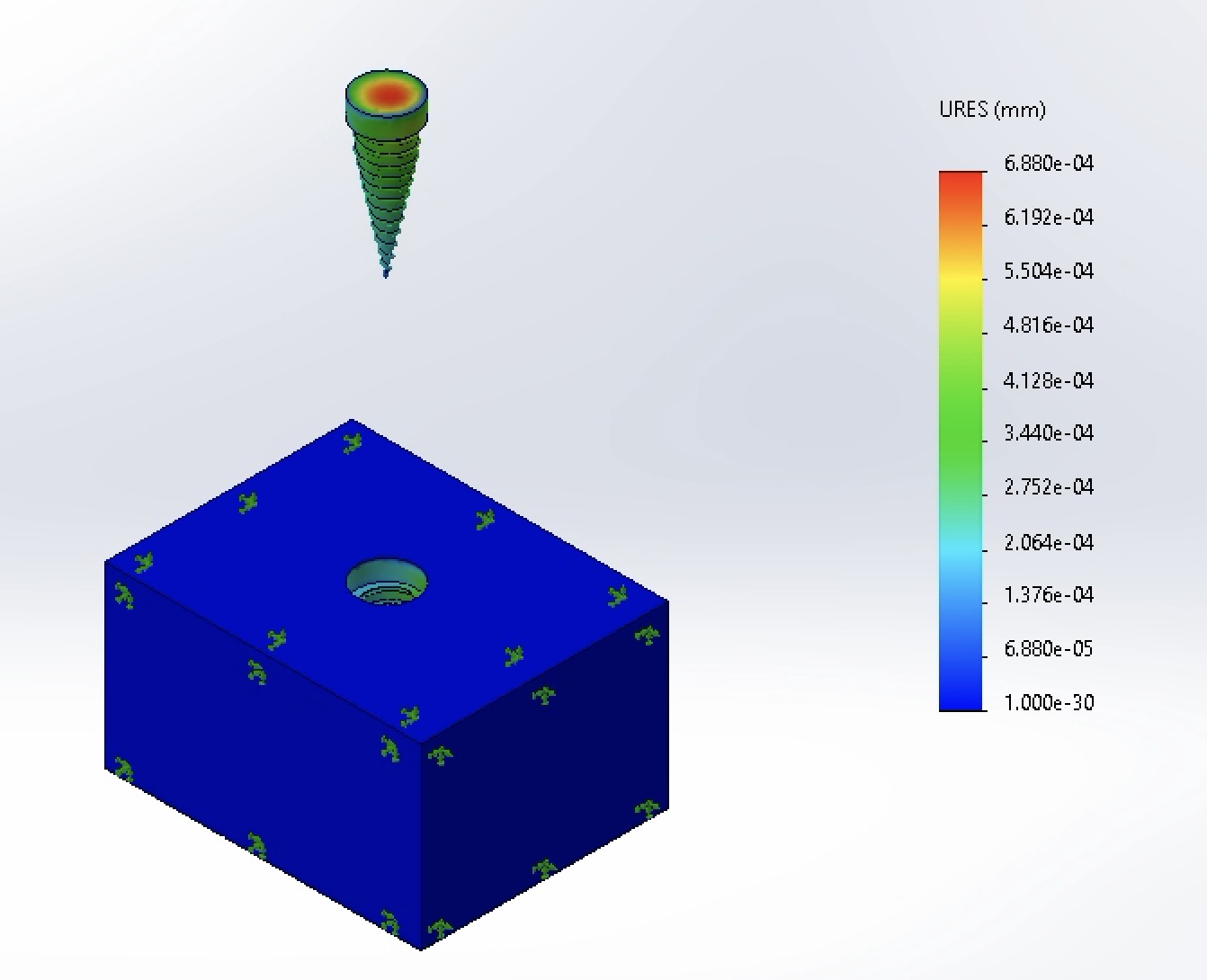
Peak displacement dropped an order of magnitude to 6.88 × 10⁻⁴ mm, providing superior mechanical stability.
-
Factor of Safety:
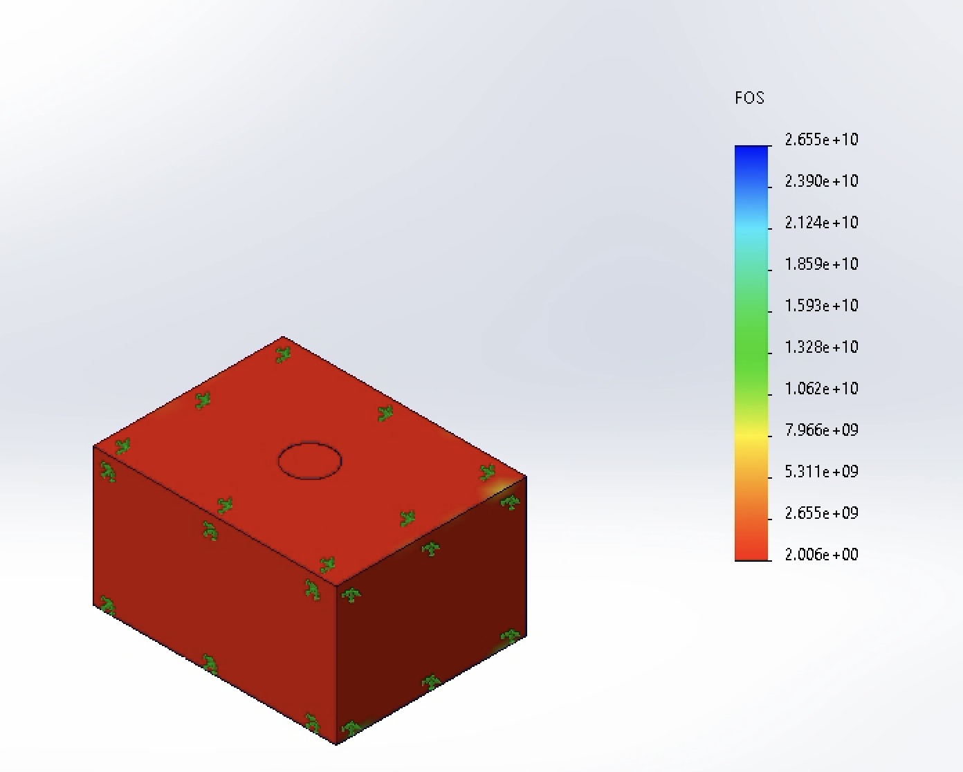
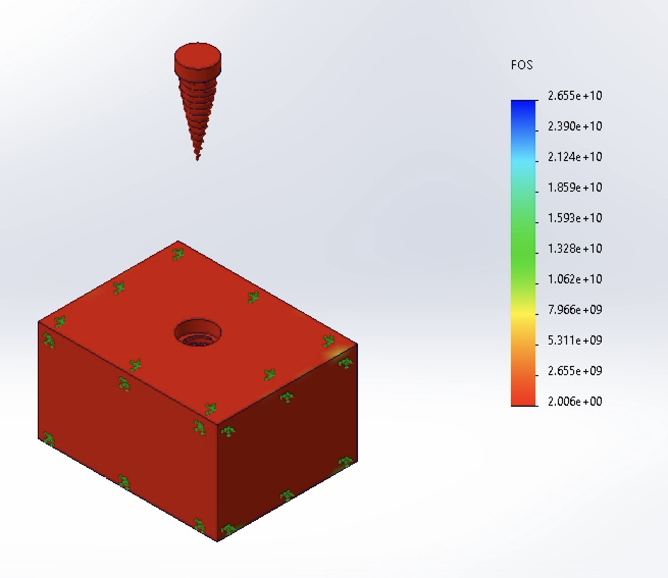
Minimum FOS reached 2.006, comfortably exceeding the 1.5 clinical safety factor requirement [2].
-
Von Mises Stress:
Final Outcome & Reflection
Outcome: By iterating the implant neck diameter in SolidWorks Simulation, I identified an optimal 4.2 mm geometry that balanced implant section modulus against cortical bone thickness—cutting peak stress to 123 MPa and boosting the minimum Factor of Safety to 2.006.
Reflection & Future Work: The unexpected stress spike in the 4.5 mm model (309 MPa) was a valuable lesson in not blindly trusting raw FEA maximum readouts without inspecting contour plots for mesh singularities and interface effects. In future iterations, I would conduct a formal mesh convergence study (h-refinement around the first thread root) and replace the idealized bonded contact assumption with a non-linear frictional contact interface to simulate immediate post-surgical loading prior to full osseointegration.
References
- Canko G, Doganay Ozyilmaz O. Impact of framework material, cantilever design, and wing configuration on stress distribution in patient-specific additively manufactured subperiosteal jaw implants: a 3D finite element analysis. BMC Oral Health. 2025;25:1816. https://doi.org/10.1186/s12903-025-07214-5
- Sun B, Zhang J, Chen P, et al. The effect of different abutment anti-rotation structures on short implant placement in cases of insufficient bone volume in the posterior maxillary region: a three-dimensional finite element analysis. BMC Oral Health. 2026;26(1):283. doi:10.1186/s12903-025-07605-8