Project Overview
This project analyzes the stress distribution in a titanium dental implant under bite-loading conditions.
Engineering Approach
The goal of this project was to analyze how an external load (representing a bite) affects stress across a dental implant and the surrounding bone.
Background
Oral health plays a significant role in overall well-being. Dental implants have emerged as a popular solution for tooth replacement, offering. a durable, biocompatible solution that preserves adjacent teeth. Finite Element Analysis (FEA) has become an essential tool in dental implant research, allowing engineers and clinicians to analyze stress distributions across varying parameters. By identifying stress concentration points, FEA helps predict failure risks such as implant fracture, bone resorption, or screw loosening before clinical testing
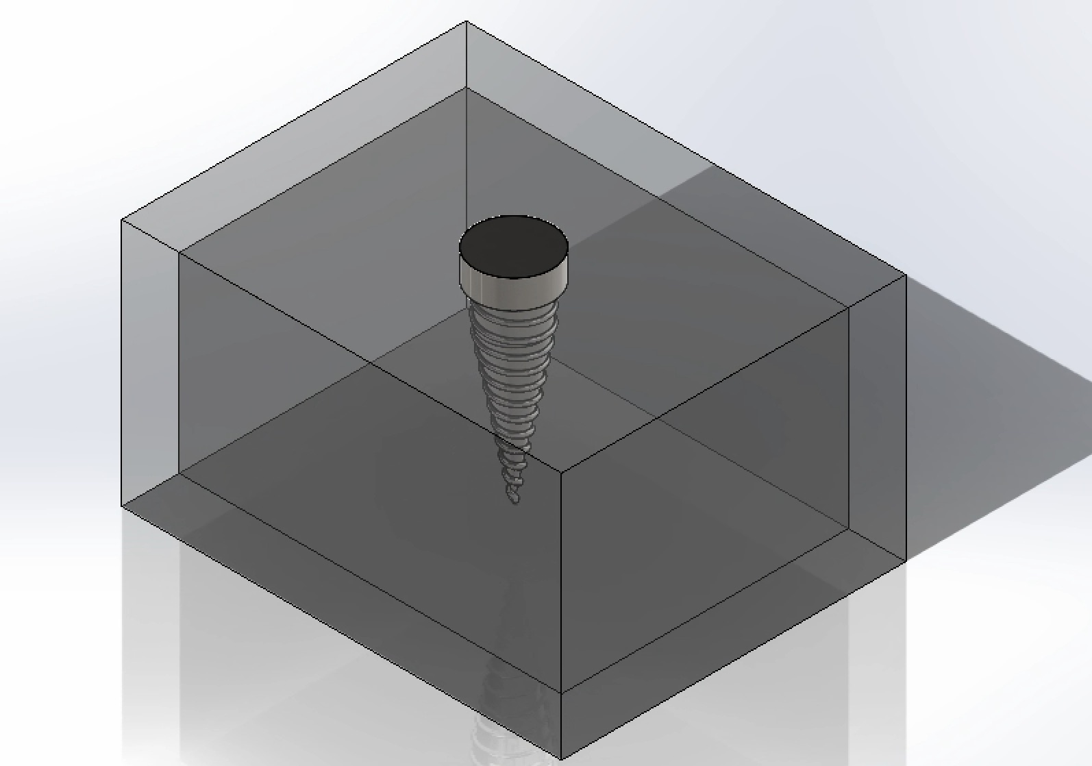
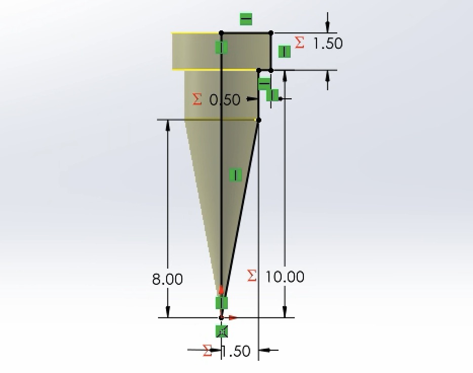
The fundamental design of the dental implant fixture used a cylindrical neck, and a threaded, tapering body. The implant fixture is embedded in the jawbone, composed of an inner cancellous layer and a surrounding cortical layer
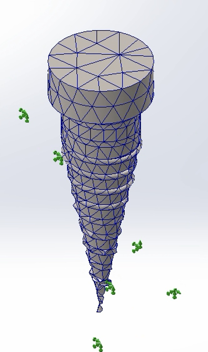
The model utilized a blended curvature-based mesh to capture the complex geometry of the threads
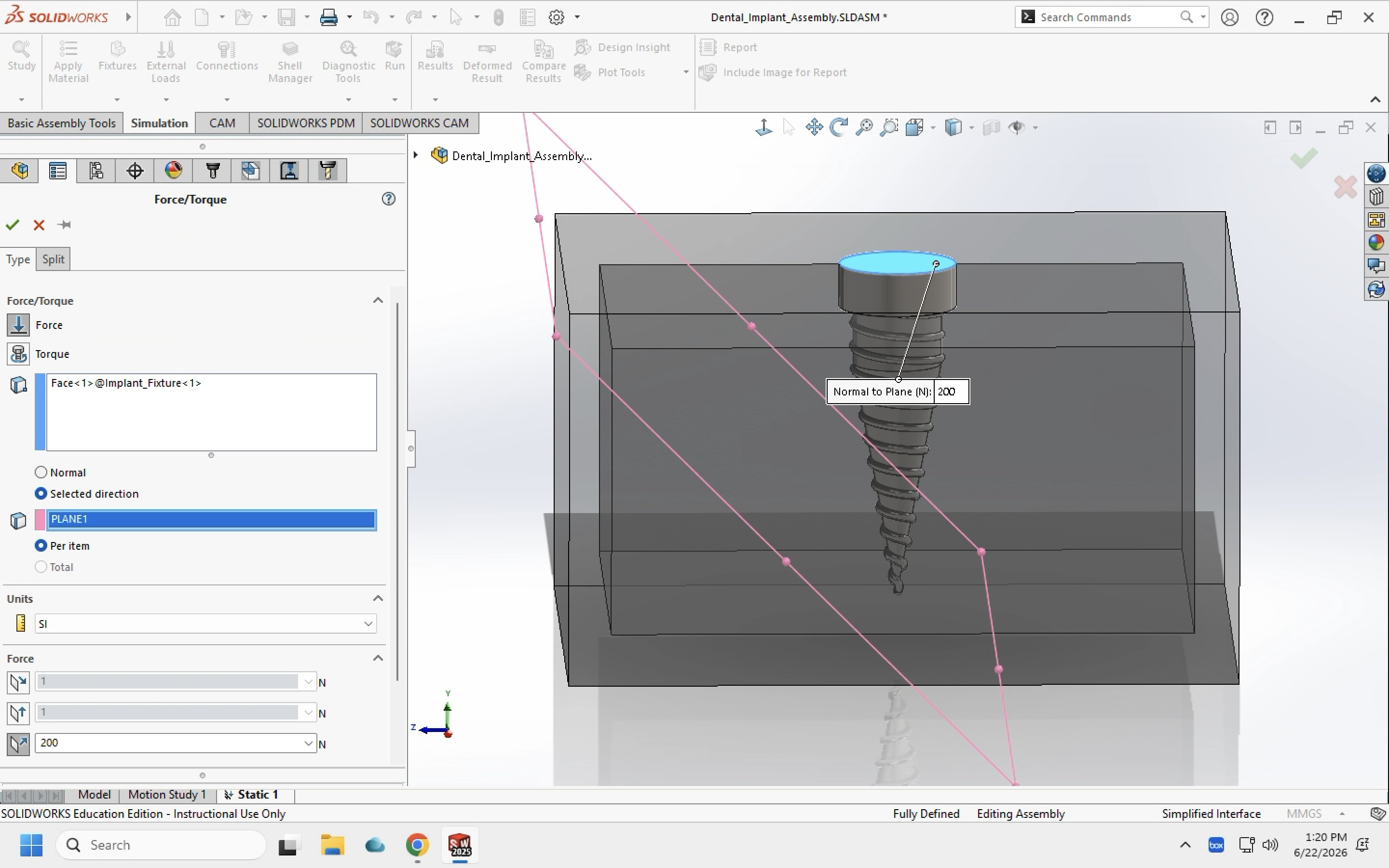
An external load of 200 Newtons was applied to the top face of the implant neck. This was at an oblique angle of 45º to simulate a realistic bite force.
Analysis Setup
- Software: SolidWorks Simulation
- Implant Material: Titanium
- Loading Condition: 200 N at 45°
- Bone Model: Cortical + cancellous bone
- Contact Assumption: Bonded interface
- Outputs: Von Mises stress, displacement, factor of safety
Material Properties
Material properties were obtained from published finite element studies of dental implants [1].
| Material | Elastic Modulus (GPa) | Poisson's Ratio | Yield Strength (MPa) |
|---|---|---|---|
| Titanium Ti-6Al-4V | 104.8 | 0.31 | 827 |
| Cortical Bone | 13.7 | .3 | 114 |
| Cancellous Bone | 1.37 | .3 | 19 |
Results Summary
| Neck Diameter | Max Stress (MPa) | Max Displacement (mm) | Min FOS |
|---|---|---|---|
| 4.0 mm | 200 | 7.97*10⁻³ | 1.143 |
| 4.5 mm | 309 | 7.39*10⁻³ | 0.831 |
| 4.2 mm | 123 | 6.88*10⁻⁴ | 2.006 |
Results
-
Standard Dimensions
Neck: 4.0 mmThe first set of results was obtained with the standard dimensions of the dental implant.
-
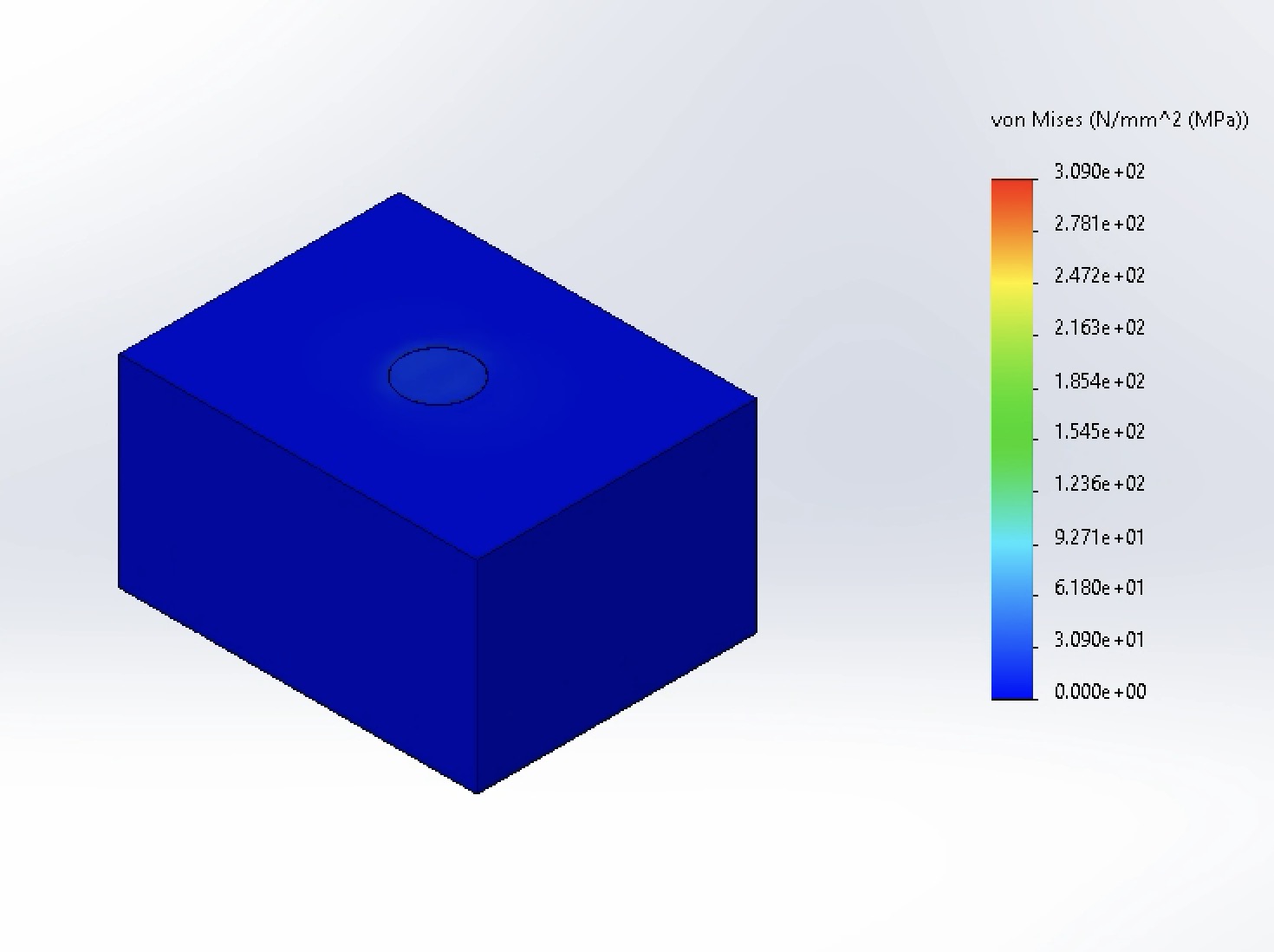
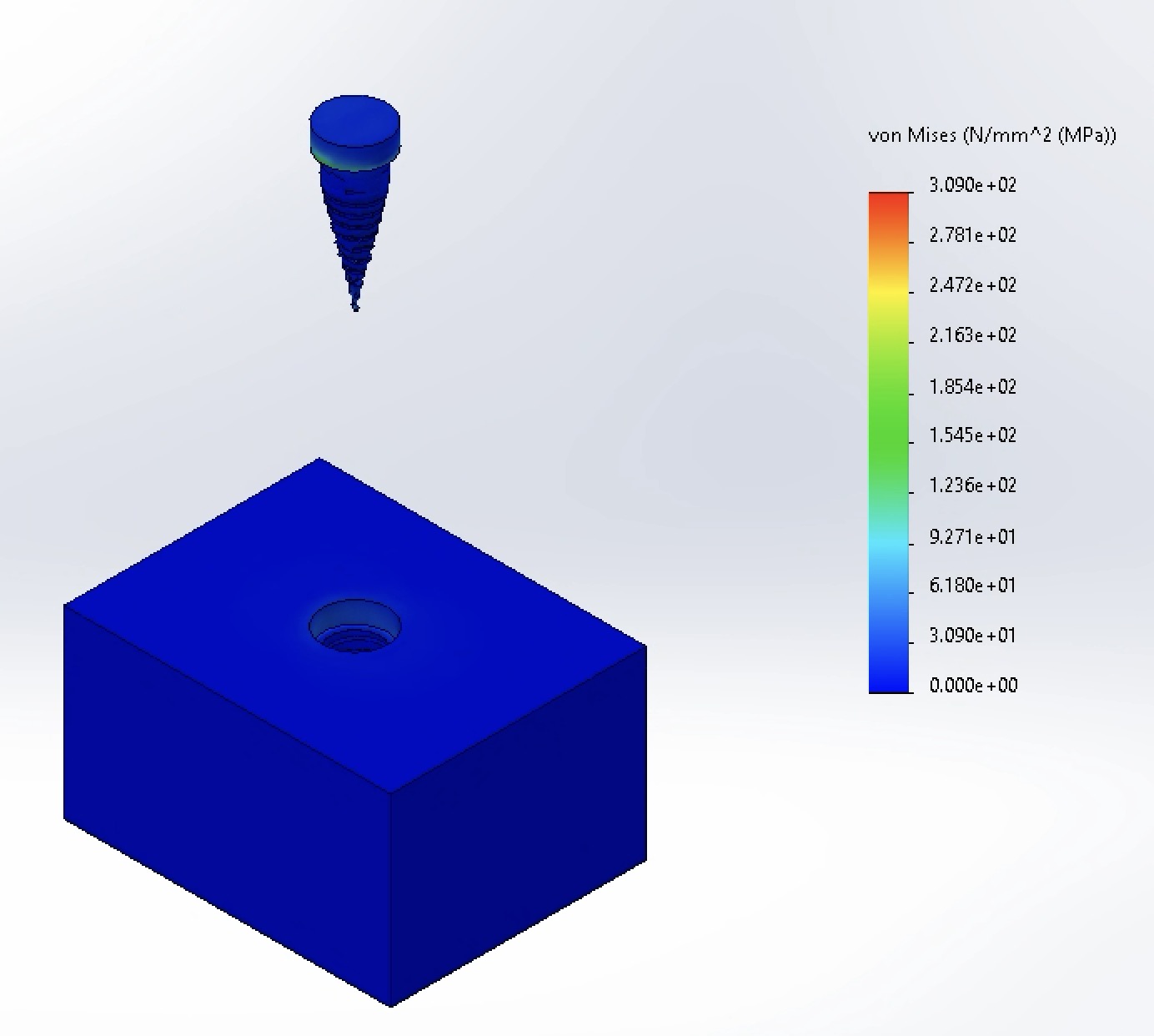
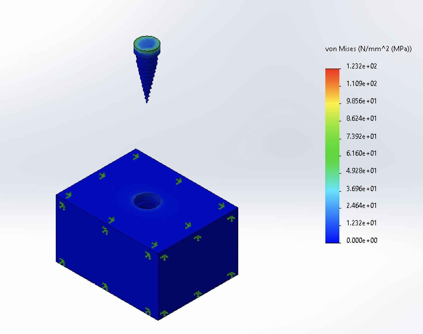
Von Mises Stress
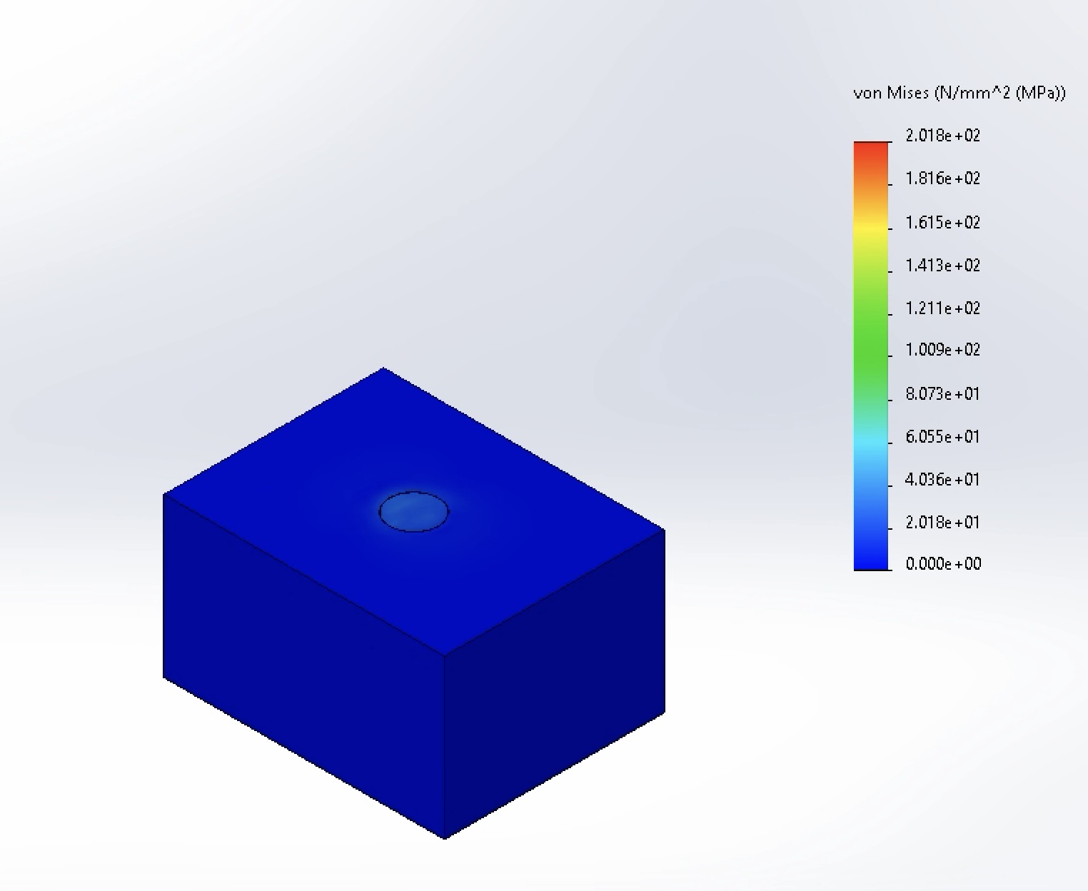
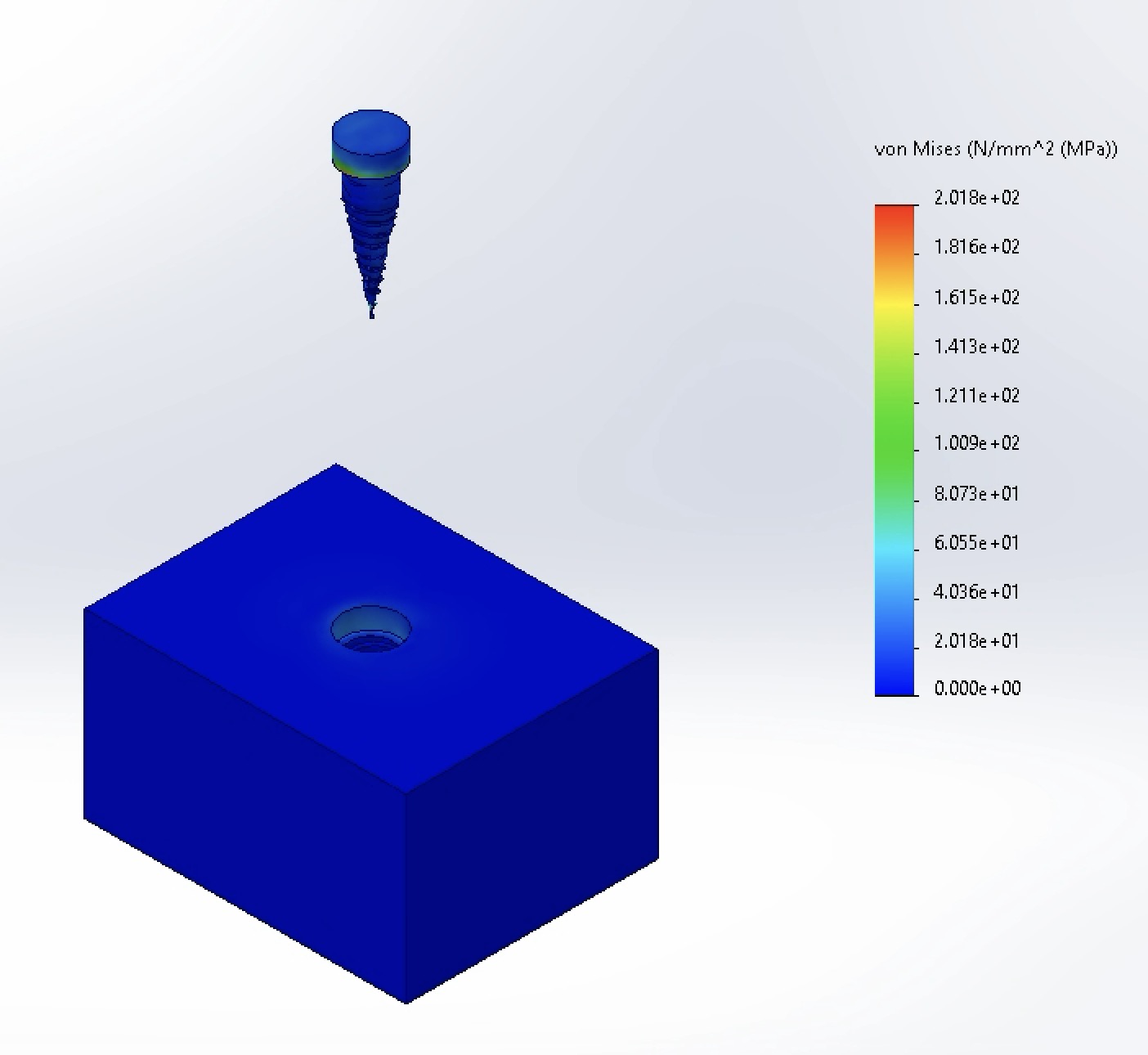
The maxiumum stress was recorded as 200 MPa. The miniumum was 0 MPa. Stress was predominantly locateed in the bottom of the neck region of the implant as well as the upper threads
-
Displacement
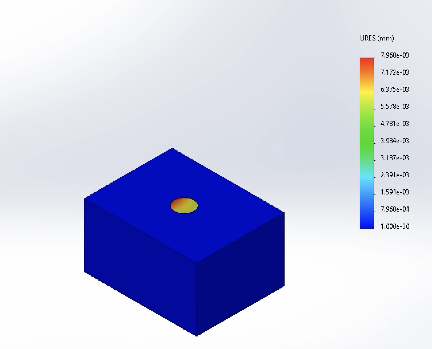
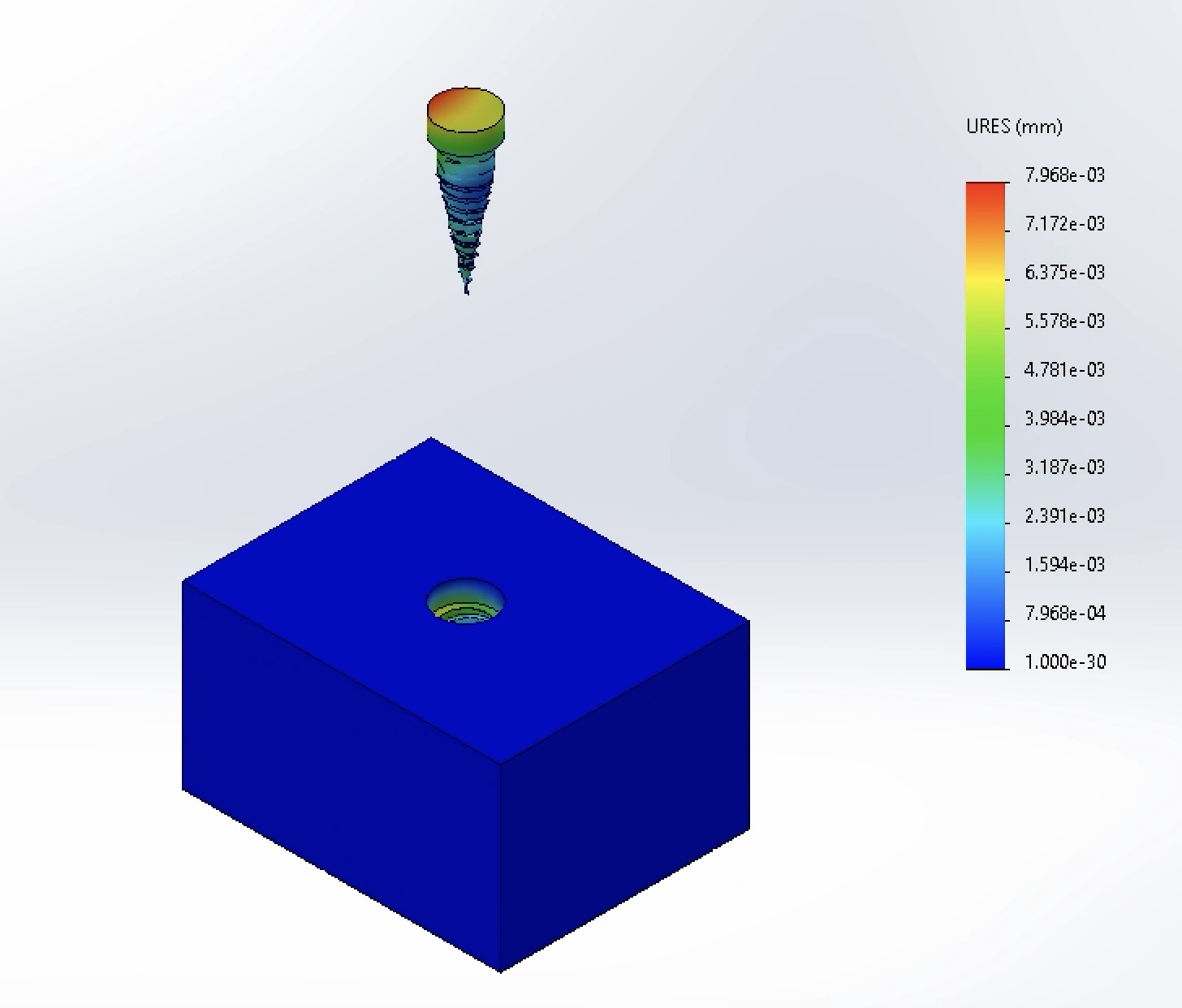
The maximum displacement was recorded as 7.968*10⁻³ mm at the head of the implant. The minimum displacement was 1*10⁻³⁰ mm. Overall, the displacement was very low, which is beneficial as an implant should not move significantly once osseointegrated.
-
Factor of Safety
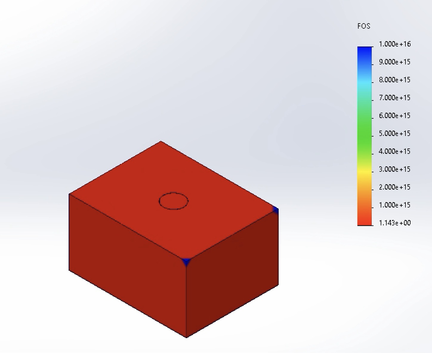
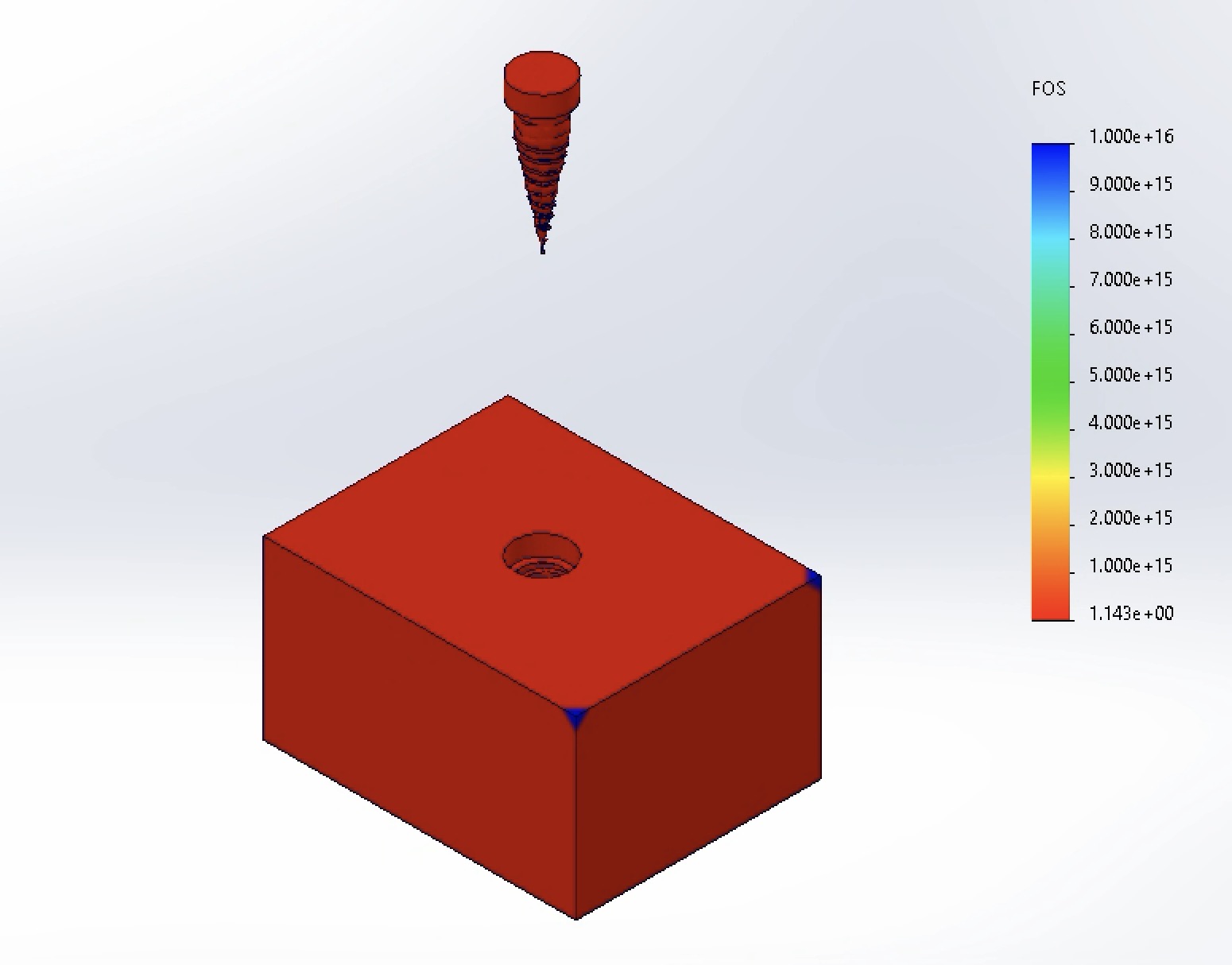
The Factor of Safety (FOS) was measured to be a minimum of 1.143. This is close to the typical range for a dental implant, though lower than would be acceptable for a clinical application. The suggested FOS is greater than 1.5 [2].
-
Von Mises Stress
- Modified Dimensions
Neck: 4.5 mm-
Von Mises Stress
The maximum stress was recorded as 309 MPa. Notably, this stress is greater than the maximum stress recorded with the standard dimensions (200 MPa). This is likely due to errors with meshing. In the image above, the higher, red, stress does not appear visibly on the figures. This elevated stress is likely localized to small pockets of the implant.
-
Displacement
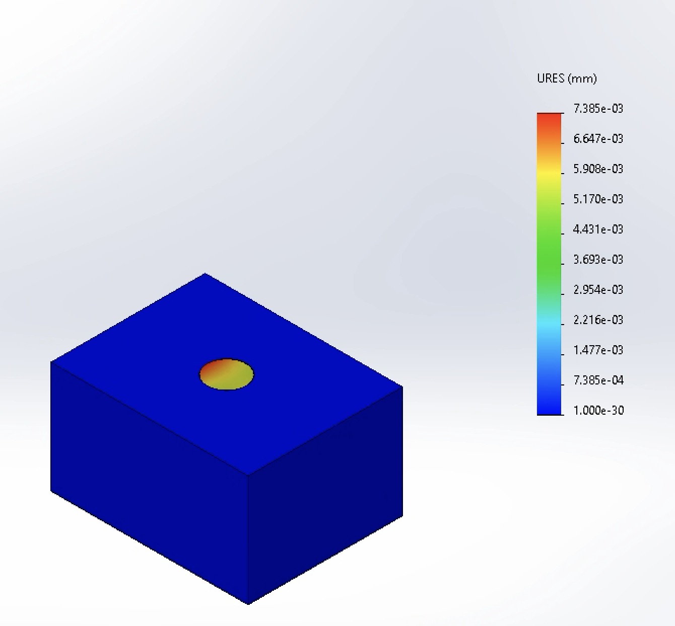
The maximum displacement was recorded as 7.385*10⁻³ mm. The displacement is notably smaller than the displacement recorded with the standard dimensions (7.968*10⁻³ mm). This is a positive outcome, as it indicates that the modified dimensions result in less movement of the implant. Additionally, it supports that the elevated maximum stress was due to the meshing errors.
-
Factor of Safety
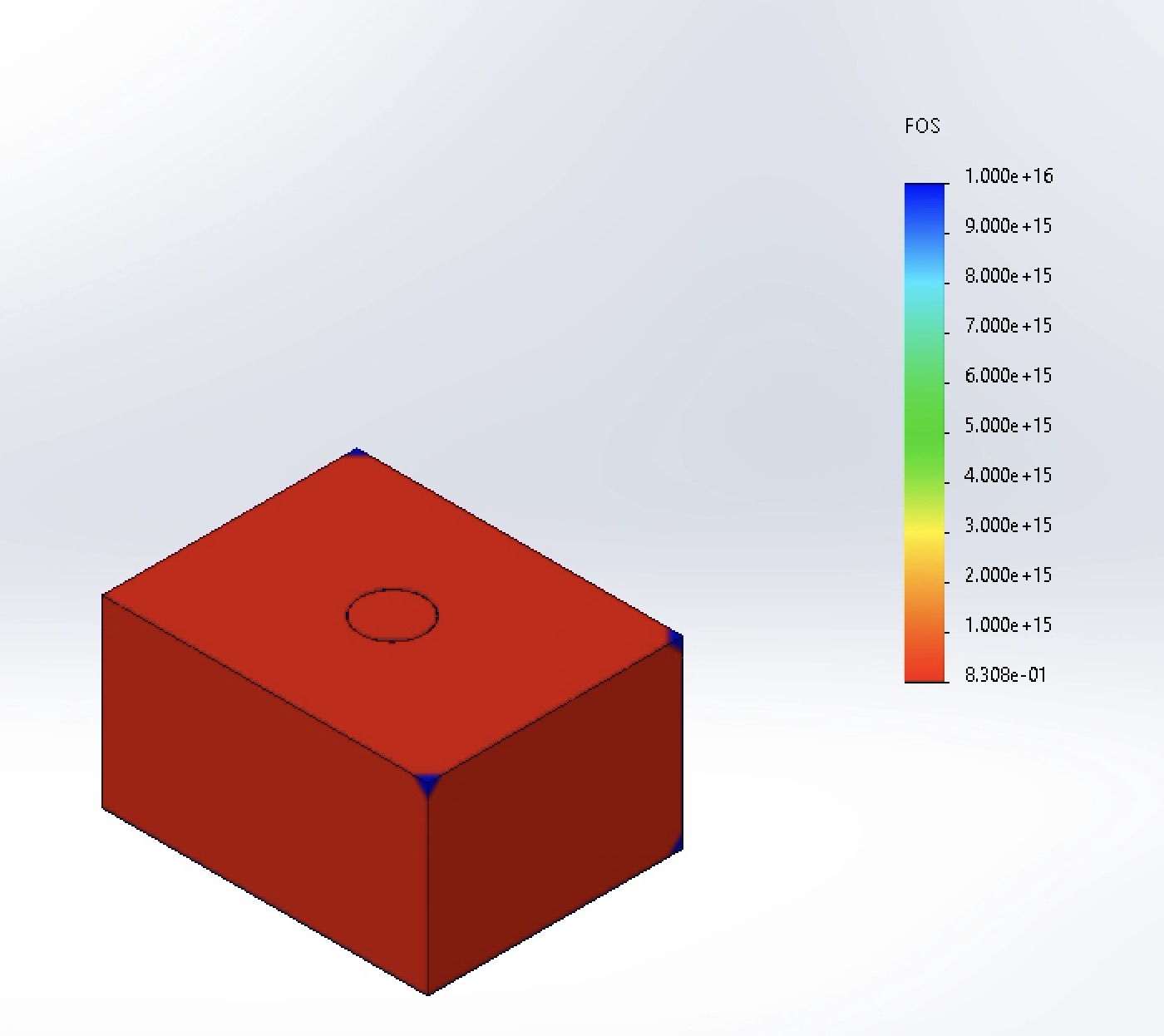
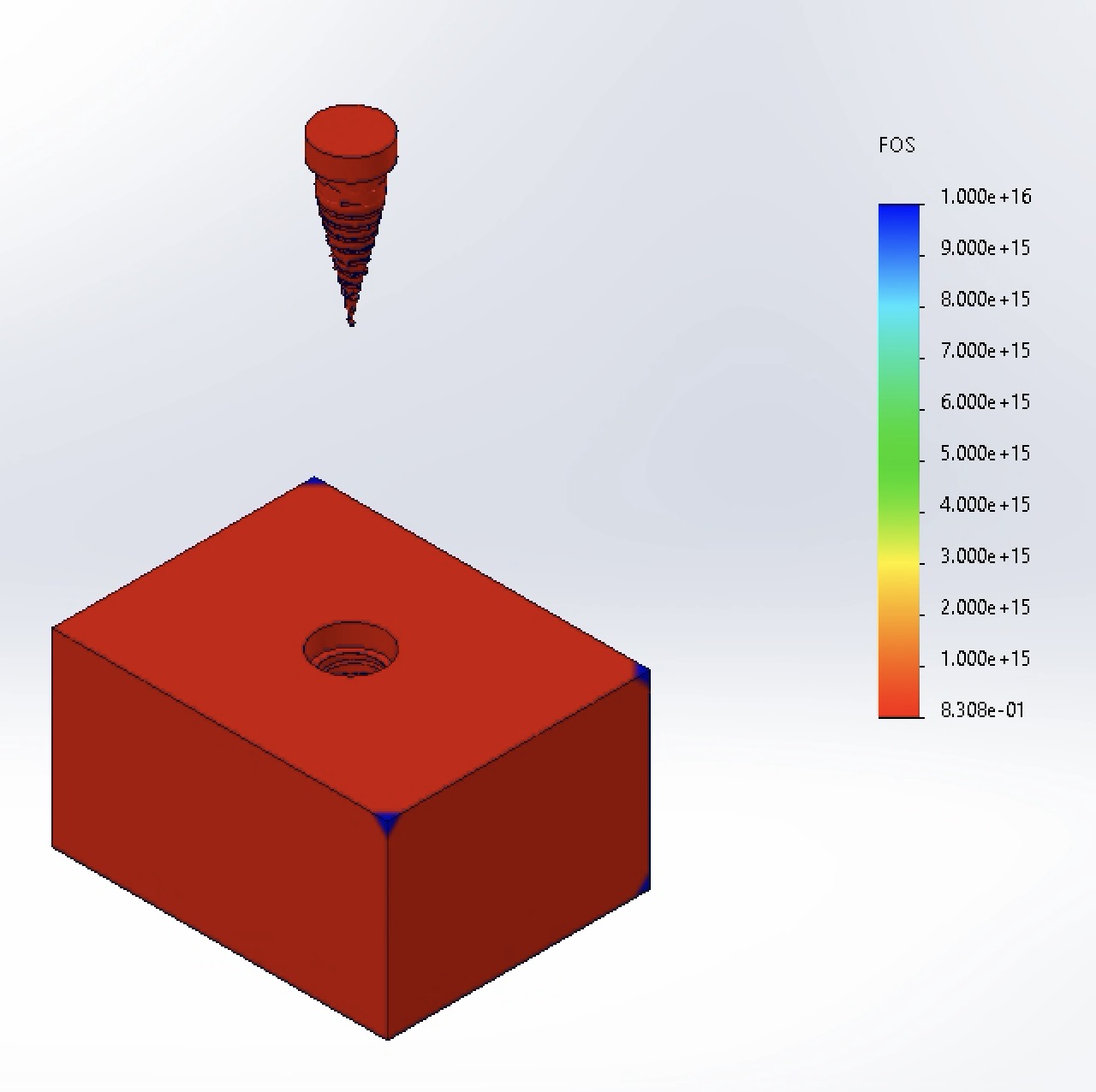
The Factor of Safety (FOS) was measured to be a minimum of 0.8308. This is smaller figure is consistent with the elevated stress. An alternative explanation is that the increased neck diameter places more stress on the surrounding bone.
-
Von Mises Stress
-
Modified Dimensions
Neck: 4.2 mm-
Von Mises Stress
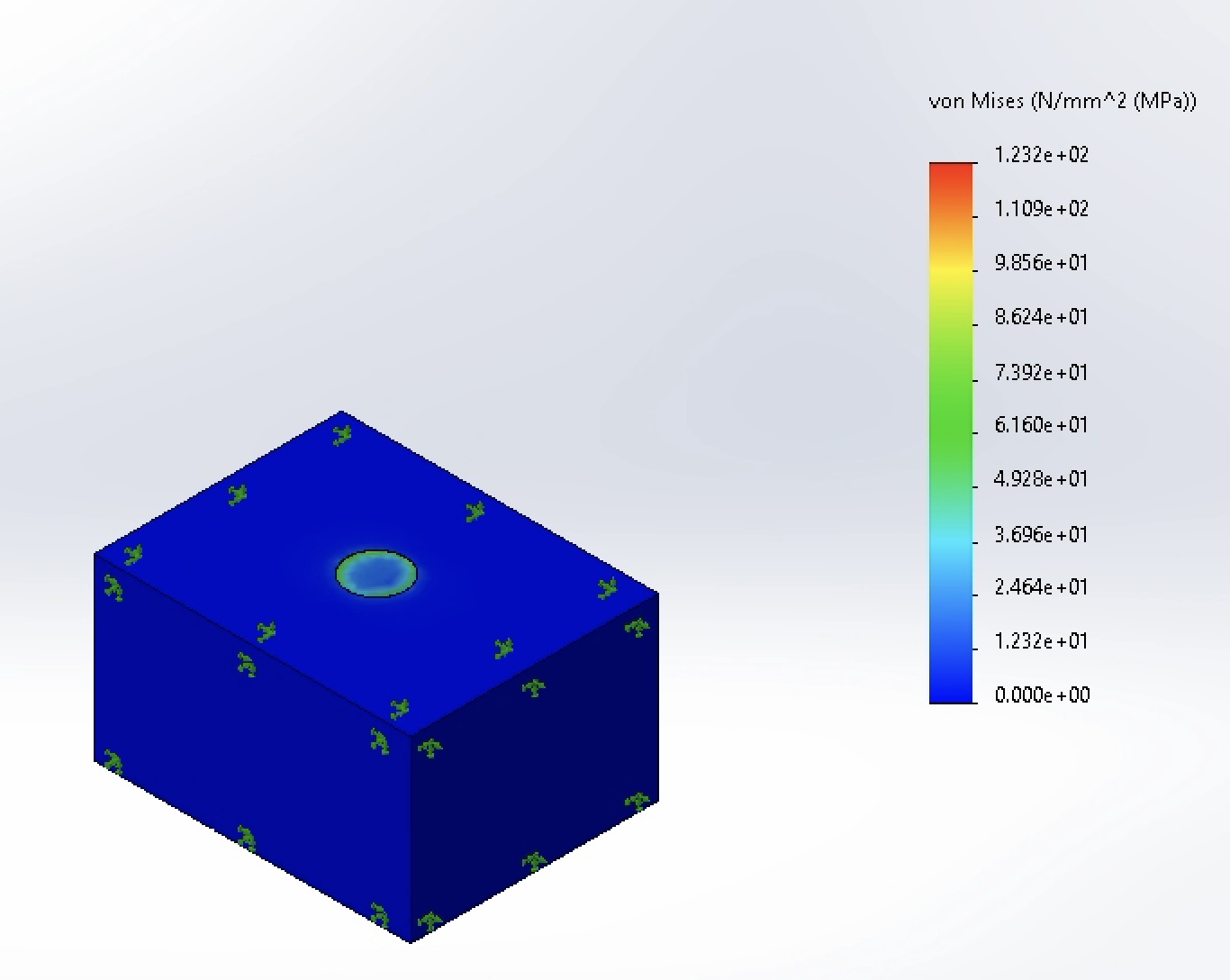
The maximum stress was recorded as 123 MPa. This is the lowest stress recorded across all modifications, indicating that the 4.2 mm neck diameter is the more effective in terms of stress distribution.
-
Displacement
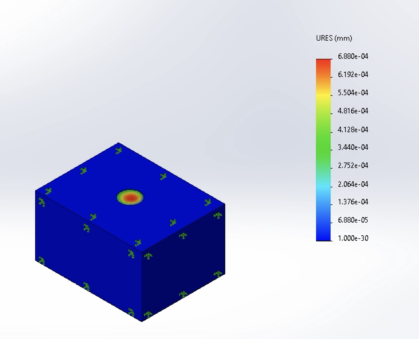
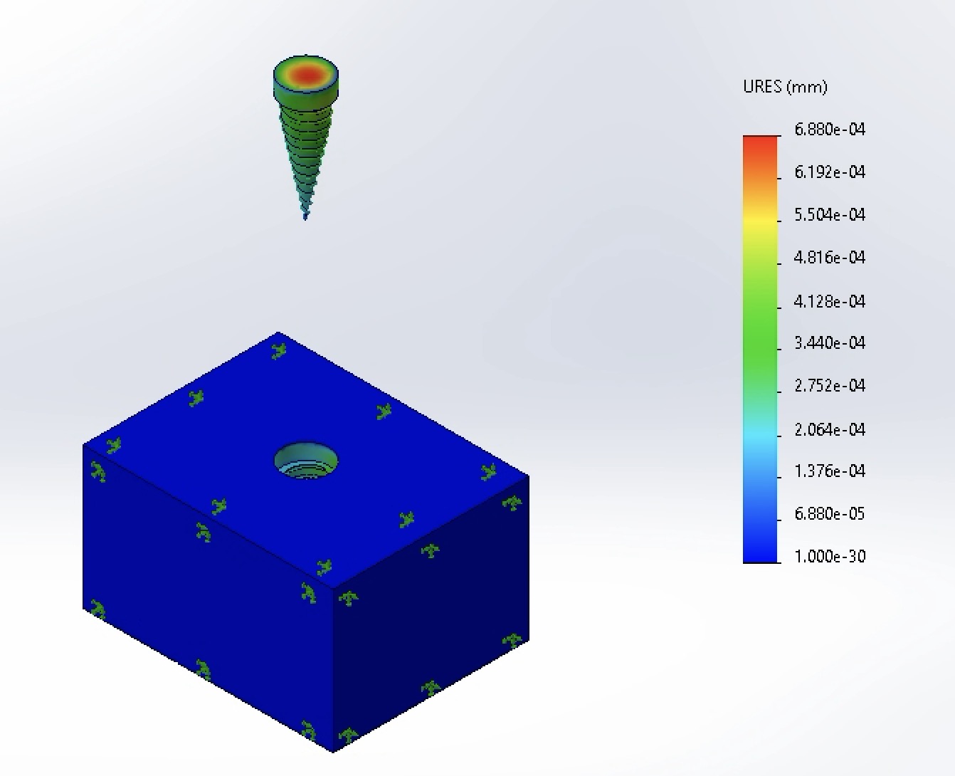
The maximum displacement was recorded as 6.88*10⁻⁴ mm. This is the lowest displacement recorded, indicating the the 4.2 mm neck diameter improves the stability of the implant.
-
Factor of Safety
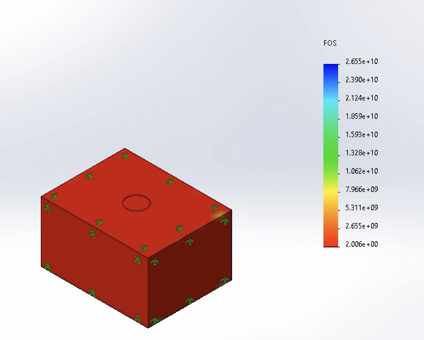
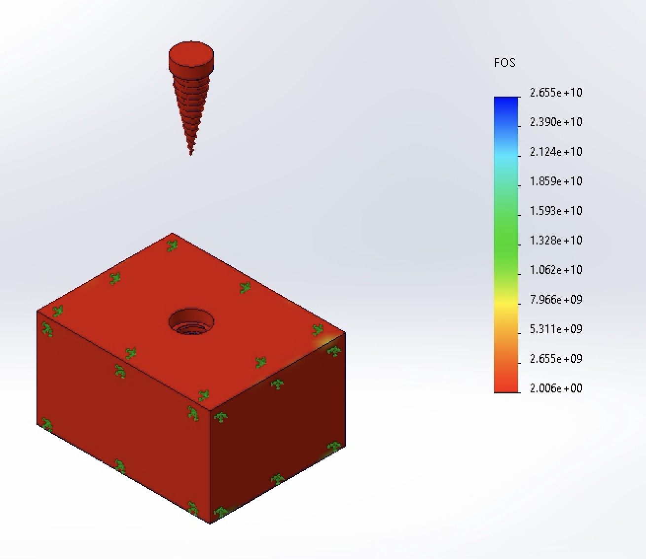
The Factor of Safety (FOS) was measured to be a minimum of 2.006. This is an improvement over the previous modification (0.8308) as well as the standard design (1.143), indicating a better safety margin with the neck design between the two diameters.
-
Von Mises Stress
Conclusion
This finite element analysis evaluated the structural performance of a dental implant system under a 200 N oblique load at 45°, with the goal of assessing stress distribution, displacement, and factor of safety across varying neck diameters.
The standard design (neck diameter 4.0 mm) demonstrated a maximum von Mises stress of 200 MPa and a minimum Factor of Safety of 1.143, indicating marginal safety under worst-case loading. Increasing the neck diameter to 4.5 mm unexpectedly resulted in a higher maximum stress of 309 MPa and a Factor of Safety below 1.0 (0.831), suggesting that the modification negatively impacted the structural integrity. This outcome was attributed to localized stress concentrations, potentially from meshing artifacts or increased load transfer to the surrounding cortical bone.
4.2 mm neck diameter yielded the most favorable results across all metrics, with a maximum stress of 123 MPa and a minimum Factor of Safety of 2.006. This configuration also produced the lowest displacement (6.88 × 10⁻⁴ mm), indicating improved stability compared to both the standard and 4.5 mm designs.
These findings demonstrate that implant neck diameter is a critical design parameter that significantly influences stress distribution and safety margins. While increasing diameter beyond a certain threshold can overload the surrounding bone, a moderate increase—from 4.0 mm to 4.2 mm—effectively reduces stress concentrations and enhances the overall safety factor. This underscores the importance of optimizing implant geometry through FEA to achieve a balance between mechanical integrity and bone preservation.
Future work should incorporate a frictional contact interface at the bone-implant junction to more accurately simulate clinical conditions and validate the upper-bound estimates provided by the bonded interface assumption.
References
- Canko G, Doganay Ozyilmaz O. Impact of framework material, cantilever design, and wing configuration on stress distribution in patient-specific additively manufactured subperiosteal jaw implants: a 3D finite element analysis. BMC Oral Health. 2025;25:1816. https://doi.org/10.1186/s12903-025-07214-5
- Sun B, Zhang J, Chen P, et al. The effect of different abutment anti-rotation structures on short implant placement in cases of insufficient bone volume in the posterior maxillary region: a three-dimensional finite element analysis. BMC Oral Health. 2026;26(1):283. doi:10.1186/s12903-025-07605-8